Lighting apparatus for generating a light pattern

Inactive Publication Date: 2012-07-05
KONINKLIJKE PHILIPS ELECTRONICS NV
View PDF2 Cites 3 Cited by
  • Summary
  • Abstract
  • Description
  • Claims
  • Application Information

AI Technical Summary

Benefits of technology

[0009]Since the light pattern is generated by diffraction at the periodic phase pattern generated by applying a voltage to the liquid crystal comprising a periodic structure, it is not necessary to provide a spatial light modulator having several pixel elements which are separately addressable. This leads to a lighting apparatus being less technically complex and, in particular, less bulky and less expensive. Moreover, although the lighting apparatus is technically less complex, it is still possible to modify the light pattern by applying a voltage to the liquid crystal cell. In particular, the light pattern can be switched on and off by switching between voltage on and off.
[0013]This allows generating different intensity distributions by modifying the voltage applied to the liquid crystal cell. In particular, the light beam originating from the light source has a beam width being similar to the beam widths of the separate light beams generated in different directions by diffraction at the generated periodic phase pattern. Thus, the beam widths of the different separate light beams generated by diffraction are preferentially the same, and their intensities can be modified by modifying the voltage applied to the liquid crystal cell.
[0017]In a DPS configuration the liquid crystal is placed between two substrates with patterned electrodes on the surfaces of the two substrates facing the liquid crystal. The voltage, i.e. the electric field, is applied across the substrates between opposing electrodes on the two substrates. This configuration provides a high design freedom of the electrode patterns, which can be used to obtain a desired electrode pattern.In an IPS configuration the liquid crystal is also placed between two substrates. However, the electrodes are located only on one of the substrates, i.e. on one surface, which faces the liquid crystal, of one substrate. Positive and negative electrodes are placed next to each other, in particular, alternately. The IPS configuration does not need a careful alignment of the electrodes on different surfaces with respect to each other.
[0018]Also in a FFS configuration a liquid crystal is placed between two substrates. However, here again the electrodes are placed only on one side of the liquid crystal, i.e. on one surface facing the liquid crystal. On a surface of the substrate facing the liquid crystal a stack is provided, wherein the stack comprises, starting from the surface of the substrate, which faces the liquid crystal, a full surface covering electrode, a dielectric layer and a patterned electrode. Also in this configuration no alignment of opposing electrodes on different substrates is necessary, and complicated electrode patterns can be obtained.
[0025]This allows increasing the variability of the light patterns, which can be generated by the lighting apparatus.
[0027]It is further preferred that the lighting apparatus comprises a control unit for controlling at least one of the light source and the voltage source such that the intensity of each of the multiple light beams generated by diffraction is below a predefined threshold. The predefined threshold is preferentially related to eye safety. The control unit can comprise a calibration curve relating the voltage to a maximum power of the light source ensuring eye safety. This allows ensuring that persons are not adversely affected by the generated light pattern. Moreover, this allows controlling the intensity of the separate light beams generated by diffraction without directly measuring the intensity of these multiple separate light beams. For example, it is not necessary to provide photodiodes for measuring the intensity of the multiple separate light beams generated by diffraction directly. This further simplifies the lighting apparatus.

Problems solved by technology

The spatial light modulator is a technically complex system which is bulky and expensive.

Method used


Image

  • Lighting apparatus for generating a light pattern
  • Lighting apparatus for generating a light pattern
  • Lighting apparatus for generating a light pattern

Examples


Embodiment Construction

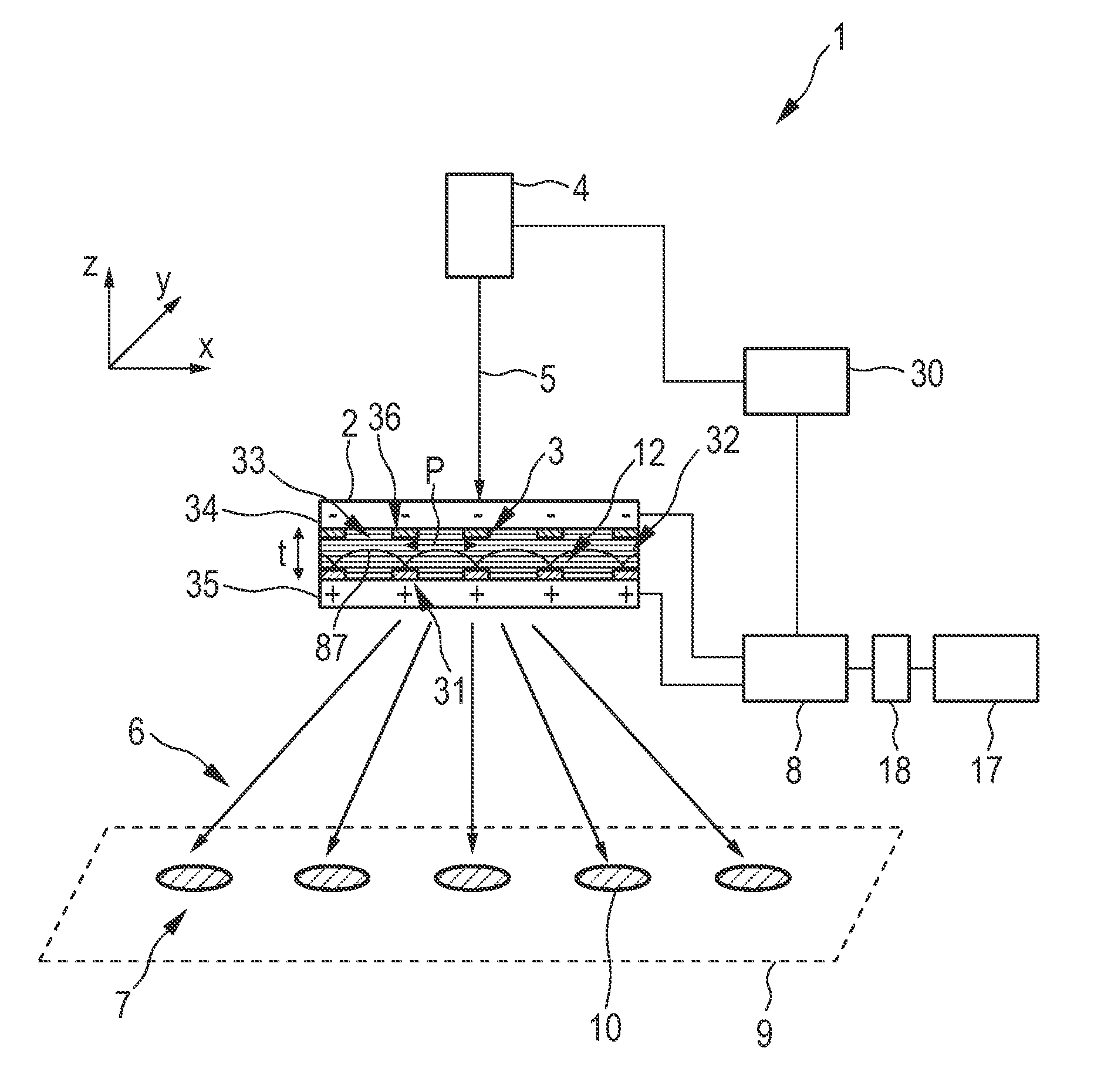
[0058]FIG. 1 shows schematically and exemplarily a lighting apparatus 1 for generating a light pattern. The lighting apparatus 1 comprises a liquid crystal cell 2 with a periodic structure 3 for generating a periodic phase pattern by applying voltage to the liquid crystal cell 2. In this embodiment, the liquid crystal cell 2 is a graded refractive index lens array using double plane switching.

[0059]The liquid crystal cell 2 comprises a liquid crystal 32 placed between a two substrates 34, 35. The surfaces of the substrates 34, 35, which face the liquid crystal 32, are provided with electrodes 31, 36 forming the periodic structure 3. The electrodes 31, 36 form the periodic structure 3. The substrates preferentially further comprise an orientation layer (not shown) to induce a macroscopic orientation of liquid crystal molecules of the liquid crystal 32. Voltage, i.e. an electric field, is applied across the electrodes 31, 36 by a voltage generator 8. The electric field leaks into outs...


PUM


Abstract

The invention relates to a lighting apparatus (1) for generating a light pattern. A light source (4) generates a light beam (5) for being directed onto a liquid crystal cell (2). The liquid crystal cell (2) comprises a periodic structure (3). If voltage is applied to the liquid crystal cell (2) by a voltage source (8), a period phase pattern is generated. The liquid crystal cell (2) and the light source (4) are adapted such that multiple separate light beams (6) are generated in different directions by diffraction at the generated periodic phase pattern, wherein the multiple separate light beams (6) form the light pattern (7). Since the light pattern is generated by diffraction at the periodic phase pattern, which is modifiable by applying voltage, different light patterns can be generated, in particular, for decorative purposes, in a technically relatively simple way.

Description

FIELD OF THE INVENTION[0001]The invention relates to a lighting apparatus, a lighting method and lighting computer program for generating a light pattern. The invention relates further to a product presentation apparatus comprising the lighting apparatus and a corresponding product presentation method for presenting a product.BACKGROUND OF THE INVENTION[0002]The Article “Enumeration of Illumination on Scanning Modes from Real-Time Spatial Light Modulators”, Li Ge et al., Vol. 7, No. 12, Optics Express, pages 403-416, 2000, discloses to use a phase-only spatial light modulator (SLM) in a Fourier-transform set-up together with fast diffractive optics design algorithms for automatically generating complex and rapidly changing laser illumination patterns in the far-field. The spatial light modulator comprises several pixel elements, wherein each pixel element allows to change the phase of the part of a coherent laser beam which meets the respective pixel element. Thus, a broad laser bea...

Claims


Application Information

Patent Timeline
IPC IPC(8): G02F1/1335
CPCA47F11/10G02F1/292G02F1/1393G02F1/139G02F1/29
InventorHIKMET, RIFAT ATA MUSTAFAVAN BOMMEL, TIESNI, YONGFENG
OwnerKONINKLIJKE PHILIPS ELECTRONICS NV