Spinning reel having improved spool oscillating mechanism

Inactive Publication Date: 2002-09-19
JOHSHUYA
View PDF1 Cites 10 Cited by
  • Summary
  • Abstract
  • Description
  • Claims
  • Application Information

AI Technical Summary

Benefits of technology

0017] It is an objective of the present invention to overcome the above-described problems and provide a spinning reel that has only a small oscillating spool pitch for each single turn of the rotor so that a long length of fis

Problems solved by technology

As a result, a great deal of force is required to turn the handle.
Also, the master gear and the pinion gear can easily break down or wear out from friction, which lessons durability of the spinning reel overall.
The spool must be made bigger in order to increase the length of fishing line wound per oscillation, but this would render the spinning reel bulky and heavy.
However, a traverse camshaft with such a narrow pitch groove would be difficult to machine and expensive to produce.
Moreover, the traverse camshaft would have low mechanical strength because the peak areas between adjacent turns of the groove are narrower, which reduces durability of the traverse camshaft.
Such a construction is not practical, because such a bulky driven gear would require an excessively bulky installation space.
Also, each acceleration or deceleration transmission results in a loss of drive force.
The intermediate transmission gear is interposed between the intermittent feed gear and the driven gear and results in a deceleration transmission to the traverse camshaf

Method used


Image

  • Spinning reel having improved spool oscillating mechanism
  • Spinning reel having improved spool oscillating mechanism
  • Spinning reel having improved spool oscillating mechanism

Examples


second embodiment

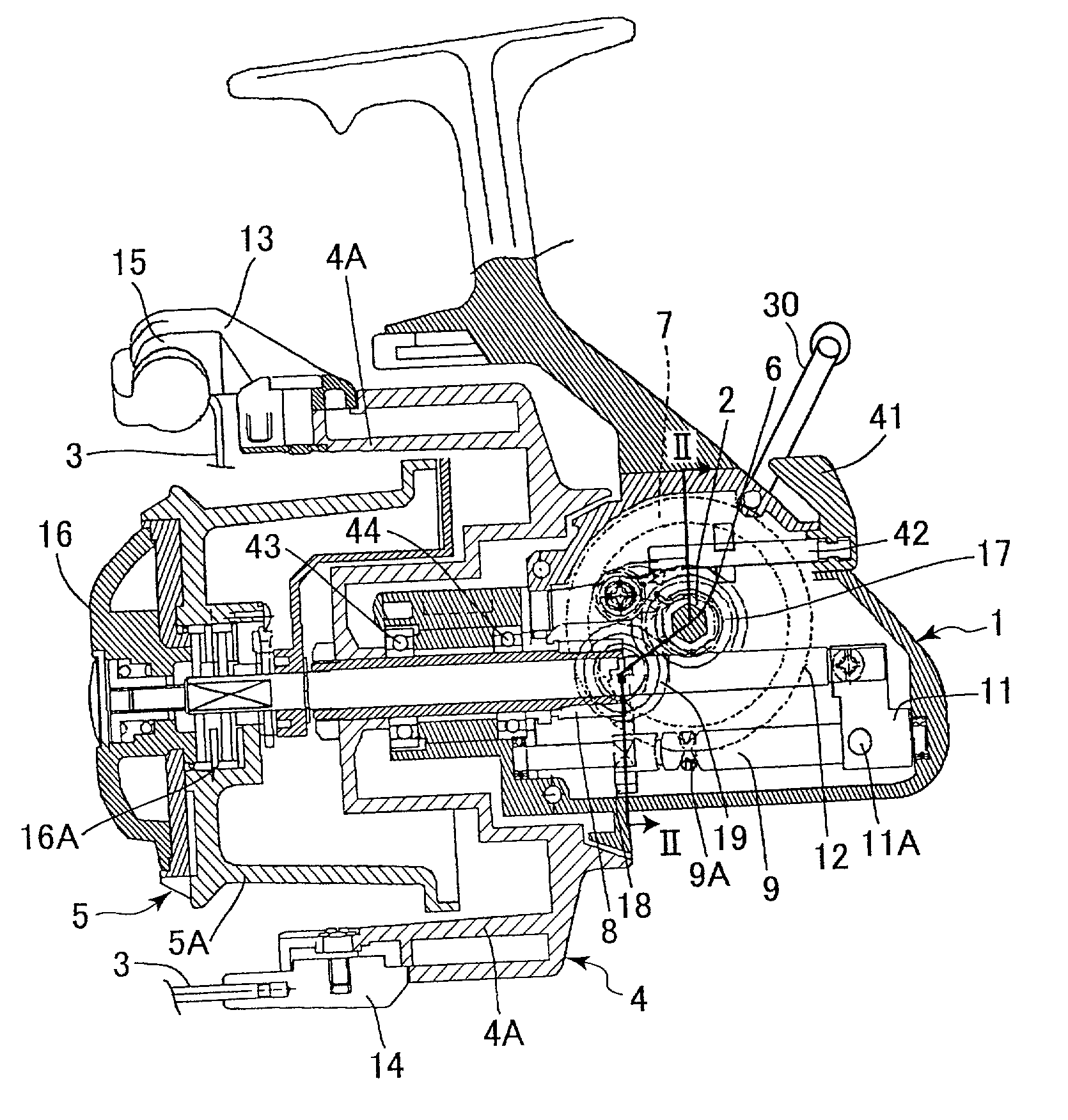
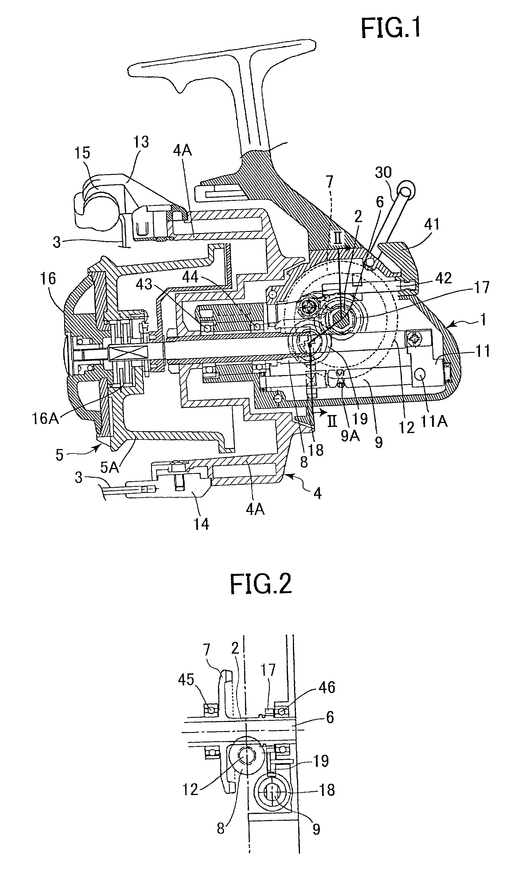
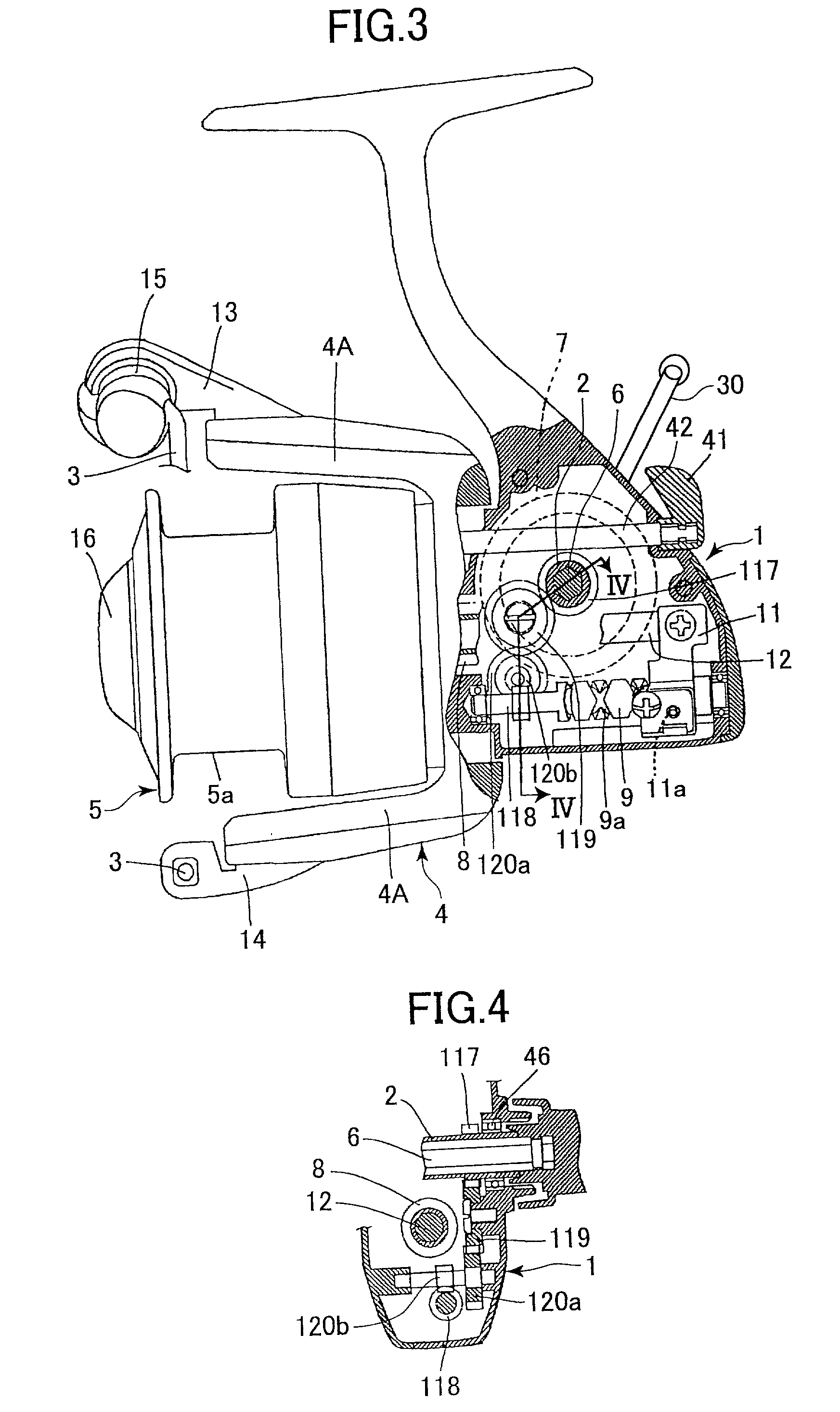
[0060] As shown in FIGS. 3 and 4, the spool oscillating mechanism of the second embodiment includes a second intermediate spiral gear 120a and a third intermediate spiral gear 120b in addition to a driving spiral gear 117, a driven spiral gear 118, and an intermediate spiral gear 119. Drive force from the driving spiral gear 117 is transmitted to the driven spiral gear 118 through the intermediate spiral gear 119, the second intermediate spiral gear 120a, and the third intermediate spiral gear 120b.

[0061] The spool oscillating mechanism of the second embodiment will be described in more detail. The driving spiral gear 117 is mounted on the shaft sleeve 2 together with the master gear 7 and has an outer diameter that is smaller than the outer diameter of the master gear 7. The intermediate spiral gear 119 is supported on the reel body 1 with its rotational axis extending between the sides of the reel body 1 and is meshingly engaged with the driving spiral gear 117. The second interme...

third embodiment

[0065] The spinning reel will be described in more detail. The shaft sleeve 2 is provided rotatably on the reel body 1 so that its rotational axis extends between the sides of the reel body 1. The driving spiral gear 217 is provided on the shaft sleeve 2 together with the master gear 7. The intermediate spiral gear 219 is provided on one end of the rotational shaft 221. The intermediate spiral gear 219 is meshingly engaged with the driving spiral gear 217. The second spiral gear 220 is provided on the other end of the rotational shaft 221 so that rotational drive from the intermediate spiral gear 219 is transmitted to the second spiral gear 220. The driven spiral gear 218 is provided on the traverse cam shaft 9, which is supported on the reel body 1 so that its rotational shaft extends in the front-to-rear direction of the reel body 1. The second spiral gear 220 is meshingly engaged with the driven spiral gear 218. With this configuration, the rotational shaft of the intermediate s...

first embodiment

[0066] Accordingly, drive force is transmitted from the driving spiral gear 217, which is formed on the shaft sleeve 2, to the intermediate spiral gear 219. As a result, the operation of driving the spool oscillating mechanism is separated from drive transmission through the master gear 7 and the pinion gear 8. As a result, the handle 30 is easier to rotate. Also, abrasion and damage to the drive transmission system, such as, to the master gear 7, can be reduced in the same manner as with the

[0067] Because drive force from the driving spiral gear 217 of the shaft sleeve 2 is transmitted to the traverse cam shaft 9 through the rotational shaft 221, which is oriented in the front-to-rear direction of the reel body 1, the traverse cam shaft 9 and other components can be positioned almost anywhere in the reel body 1 without increasing the side-to-side thickness of the reel body reel body 1, by merely changing the tilt angle or the length of the rotational shaft 221. This enhances freedo...


PUM


Abstract

A spinning reel with a handle shaft rotatably supported in a reel body. The handle shaft is connected with a handle. A master gear and a driving spiral gear are provided at separated positions on the handle shaft. The master gear is meshingly engaged with a pinion gear provided integrally with a rotor at the front of the reel body so that rotation of the handle rotates the rotor. A spool shaft fixed with a spool extends in a frontward/rearward direction of the reel body and is oscillatingly movably supported on the reel body. A traverse camshaft is rotatably supported by the reel body. The traverse camshaft is fixedly provided with a driven spiral gear and is formed with a cam groove. A slider member is fixed to the spool shaft and has a pawl engaged with the cam groove so that the slider member is driven to move along the length of the traverse camshaft by rotation of the traverse camshaft. At least one intermediate spiral gear is provided for transmitting rotation of the driving spiral gear to the driven spiral gear.

Description

BACKGROUND OF THE INVENTION[0001] 1. Field of the Invention[0002] The present invention relates to a spinning reel, and more particularly to a spool oscillating mechanism in the spinning reel.[0003] 2. Description of the Related Art[0004] A spinning reel generally includes a reel body, a spool, a rotor, and a handle. The spool and the rotor are provided at the front end of the reel body. Rotating the handle rotates the rotor around the outside of the spool and oscillates the spool in its axial direction. Rotation of the rotor wraps fishing line, via a fishing line guide of the rotor, around a fishing line winding portion of the spool. The oscillating movement of the spool ensures that the fishing line is wrapped evenly over the entire fishing line winding portion.[0005] To achieve this fishing line winding operation, the spinning reel includes a handle shaft, a spool shaft, a master gear, a pinion gear, and a spool oscillating mechanism. The handle shaft is rotatably supported on th...

Claims


Application Information

Patent Timeline
IPC IPC(8): A01K89/01
CPCA01K89/0114
Inventor NODA, HIDEOSAEKI, MASAHIROOKADA, ATSUHITO
Owner JOHSHUYA
Why Eureka
Try Eureka