Decoration panel and method for manufacturing decoration panel

a technology of decoration panel and decoration panel, which is applied in the direction of transportation and packaging, other domestic articles, synthetic resin layered products, etc., can solve the problems of long time and low productivity, and achieve the effect of high design freedom and easy production

Active Publication Date: 2016-03-31
YAMAHA FINE TECHNOLOGIES CO LTD
View PDF16 Cites 10 Cited by
  • Summary
  • Abstract
  • Description
  • Claims
  • Application Information

AI Technical Summary

Benefits of technology

[0009]The present invention has been made in consideration of the circumstances described above, and an object of the present invention is to provide a decoration panel which can be easily produced with high freedom of design, and a manufacturing method thereof.
[0017]According to the present invention, a decoration panel can be easily produced with high freedom of design.

Problems solved by technology

In the technology disclosed in Japanese Unexamined Patent Application, First Publication No. 2003-326897, it takes a long time to fill the window hole with the inlay member, or it is necessary to accurately match the dimensions of the inlay member and the window hole, and thus productivity is low.

Method used


Image

  • Decoration panel and method for manufacturing decoration panel
  • Decoration panel and method for manufacturing decoration panel
  • Decoration panel and method for manufacturing decoration panel

Examples


first embodiment

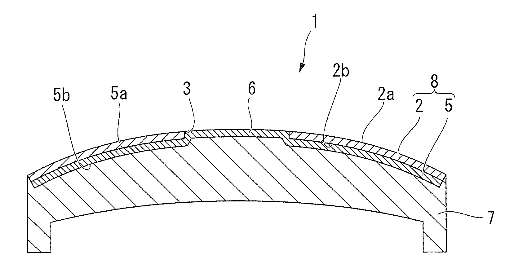
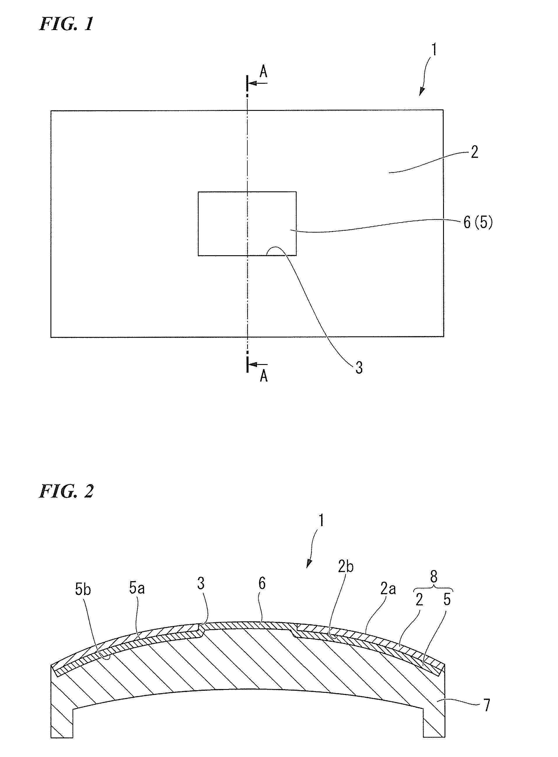
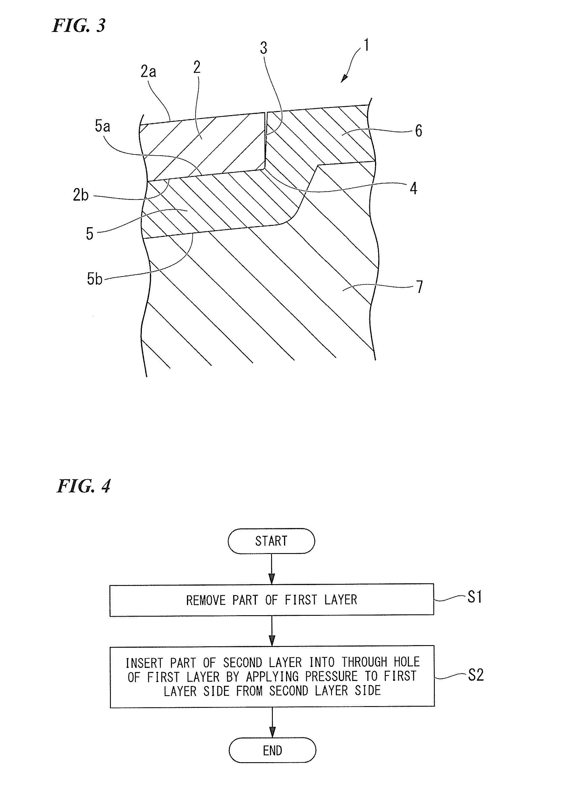
[0030]A first embodiment of the present invention will be described. FIG. 1 is a plan view of a decoration panel of this embodiment. FIG. 2 is a sectional view cut along line A-A of FIG. 1. FIG. 3 is an enlarged view of FIG. 2.

[0031]As illustrated in FIG. 1 and FIG. 2, a decoration panel 1 includes an outer layer 2, a decoration layer 5, and a molded resin layer 7.

[0032]The decoration panel 1 is a panel in which the molded resin layer 7 in contact with the decoration layer 5 is integrated with a stacked body 8 formed by stacking the outer layer 2 and the decoration layer 5 in this order using insert molding.

[0033]The outer layer 2 illustrated in FIG. 3 is a sheet-like member having a decoration on a front side 2a. A through hole 3 is formed in the outer layer 2 to be opened to both of the front side 2a and a side opposite thereto (a back side 2b). In this embodiment, the outer layer 2 is formed of a wooden material. The decoration of the front side of the outer layer 2 exemplified i...

modification example

[0054]Next, a modification example of the embodiment described above will be described.

[0055]The shape of the molding die M is not limited to the shapes described in the embodiment described above. For example, according to a molding die including a first molding surface which is in contact with the front side 2a of the first layer 2A, and a second molding surface lower than the first molding surface, an inlay pattern is formed by insert molding in which the second layer 5A protrudes from the front side 2a of the first layer 2A. A manufacturing method of the decoration panel of this modification example is able to easily form an inlay pattern having excellent appearance with high accuracy such that an inlay member is inserted into a groove without having a gap.

second embodiment

[0056]A second embodiment of the present invention will be described. FIG. 9 is a plan view illustrating a decoration panel of this embodiment. FIG. 10 is a sectional view cut along line B-B of FIG. 9.

[0057]As illustrated in FIG. 9 and FIG. 10, a configuration of a decoration panel 11 is different from that of the first embodiment described above in that an inner layer 9 is provided between the decoration layer 5 and the molded resin layer 7.

[0058]The decoration panel 11 is a panel in which the molded resin layer 7 is integrated with a stacked body 10 formed by stacking the outer layer 2, the decoration layer 5, and the inner layer 9 in this order by the insert molding such that the molded resin layer 7 is in contact with the inner layer 9.

[0059]The inner layer 9 is a sheet-like member arranged on an outer surface of the decoration layer 5 (the back side 5b) on a side opposite to a surface (the front side 5a) which is in contact with the outer layer 2. The inner layer 9 has an appro...


PUM

PropertyMeasurementUnit
thicknessaaaaaaaaaa
injection pressureaaaaaaaaaa

Abstract

A decoration panel of the present invention includes an outer layer having a through hole formed thereon which is opened to a front surface to be decorated and a back surface on a side opposite to the front surface, and a decoration layer including an inlay pattern portion which is part of the decoration layer entering the inside of the through hole from the back surface side being curved and deformed, the decoration layer being arranged on the entire back surface of the outer layer and having an approximately uniform layer thickness.

Description

BACKGROUND OF THE INVENTION[0001]1. Field of the Invention[0002]The present invention relates to a decoration panel and method for manufacturing a decoration panel.[0003]Priority is claimed on Japanese Patent Application No. 2014-201153, filed Sep. 30, 2014, the content of which is incorporated herein by reference.[0004]2. Description of Related Art[0005]In the related art, a manufacturing method of a decoration panel is known in which a through hole is formed in part of an outer layer of a stacked body formed by superimposing a plurality of layers which are different from each other, and an inner layer is designed to be seen through the through hole of the outer layer (for example, refer to U.S. Pat. No. 6,633,019 B1).[0006]In the method disclosed in U.S. Pat. No. 6,633,019 B1, part of the outer layer is removed from a composite body formed by stacking the outer layer and the inner layer via laser processing such that the through hole having a predetermined design pattern is formed...

Claims


Application Information

Patent Timeline
Patent Type & Authority Applications(United States)
IPC IPC(8): B32B3/26B29C65/00B29C65/48B29C70/78B32B15/08
CPCB32B3/266B32B15/08B29C65/48B29C66/0326B29L2009/00B29C66/0324B32B2451/00B29K2105/256B29L2031/722B29C70/78B32B3/30B32B15/10B32B37/10B44C1/26B44C5/0415B44C5/043B44C5/0453B29C45/1418B29C2793/0054B29C2793/0081B29C2793/009B32B3/28B32B15/20B32B21/08B32B27/00B32B2607/00Y10S428/9133Y10T428/22Y10T428/24066Y10T428/24331Y10T428/24339Y10T428/24521Y10T428/24736Y10T428/31703B29C45/14811B29C2045/14237B29C2045/14868B29C2045/14934B29K2705/00B29K2711/14B29L2007/002B29L2009/003B32B21/04B32B21/14B32B37/12B32B37/18B32B38/06B32B38/10B44C3/005B44C3/08B44C3/10B44C5/005
Inventor HAMADA, YUTAKASAMIZO, AIKOMARUYAMA, YOSHIHISAHIRATO, MASAHIRO
Owner YAMAHA FINE TECHNOLOGIES CO LTD
Why Eureka
Try Eureka