Rotary throttle valve carburetor

a technology of rotary throttle valve and carburetor, which is applied in the field of carburetors, can solve the problems of limiting requirements, limiting design freedom, and excessive or undetectable force required to operate the throttle, and achieves the effects of reducing the size of the carburetor, and being easy to moun

Inactive Publication Date: 2006-03-07
NIPPON WALBRO KK
View PDF21 Cites 10 Cited by
  • Summary
  • Abstract
  • Description
  • Claims
  • Application Information

AI Technical Summary

Benefits of technology

[0007]In one form, a driven gear formed on the upper end of the throttle valve and a drive gear connected to a shaft on which a valve lever of the throttle valve is mounted are meshed with each other, and the gears are disposed in an encasing chamber sealed by a lid plate to prevent dust or the like from fouling a valve chamber and the rotary throttle valve. An accelerating pump may be provided, and may be driven by a cam on the lower surface of the drive gear is disposed between the rotary throttle valve and the shaft on which the valve lever of the throttle valve is mounted to permit the size of the carburetor to be minimized.
[0008]According to another embodiment of a carburetor, a fuel adjustment needle valve is secured in place to prevent tampering or inadvertent rotation of the valve. An antiturning body is held in a holding hole formed on a pump cover plate, and after setting the position of an adjustment bolt, a spline hole formed on the antiturning body is fitted on a spline shaft portion of the adjustment bolt. An antiturning piece formed on the antiturning body is received in a groove in the carburetor body to prevent turning of the antiturning body and the adjustment bolt.
[0009]According to another aspect of the invention, a remote control throttle cable holder includes a receiving cylinder for receiving an end of an outer tube of the remote control cable, and an insert port in communication with the receiving cylinder through a slit is provided on the cable holder whereby the end of the inner wire is engaged with the slit when an end of the inner wire is mounted on a swivel of a throttle valve lever. The outside diameter of the slit is smaller than that of the end of the inner wire, therefore the outer tube is held on the cable holder so as not to fall off, and thus the cable is easy to mount to the cable holder.
[0010]Some potential objects, features and advantages of the invention include providing a carburetor in which a rotary throttle valve can be rotated smoothly, which is small and compact in size, has high design freedom, provides a fuel adjustment needle valve for a carburetor which prevents user tampering with a calibrated setting, and is of reltaively simple design and economical and easy manufacture and assembly.

Problems solved by technology

In the conventional rotary throttle valve carburetor, moving the rotary throttle valve via a link or lever mechanism, an excessive or undesirably high force may be required to operate the throttle, which can be a limiting requirement in design.
This limits the design freedom as far as shape of the cam and the type of mateiral that can be used.
The above-described fuel adjustment needle valve of a carburetor poses a problem that the plug or cap is difficult to process and assemble.
However, it is difficult to mount and retain the inner wire in the groove 106 of the swivel 105 since the surrounding space is narrow and crowded, and the split groove 106 is small.

Method used


Image

  • Rotary throttle valve carburetor
  • Rotary throttle valve carburetor
  • Rotary throttle valve carburetor

Examples


Embodiment Construction

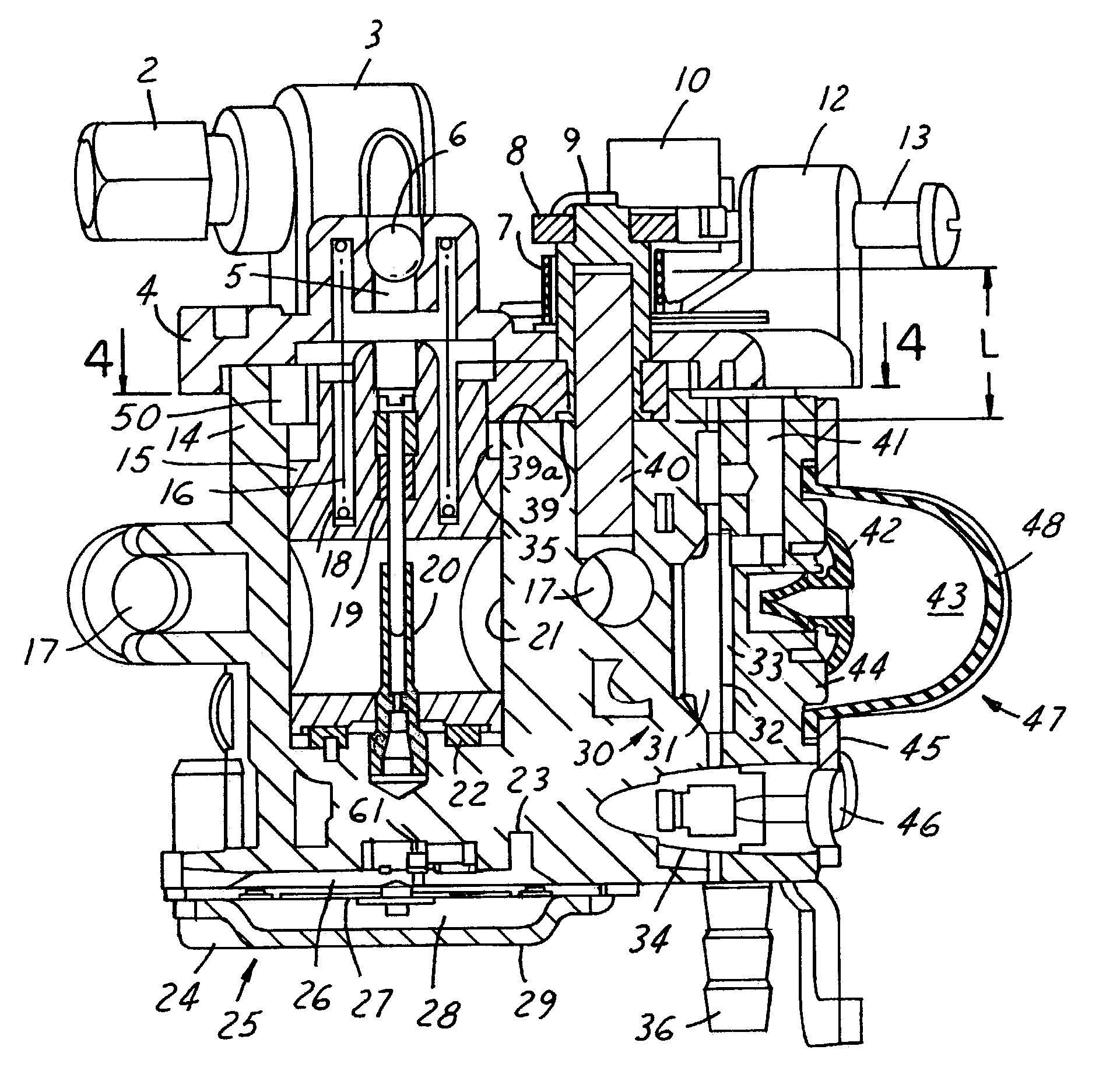
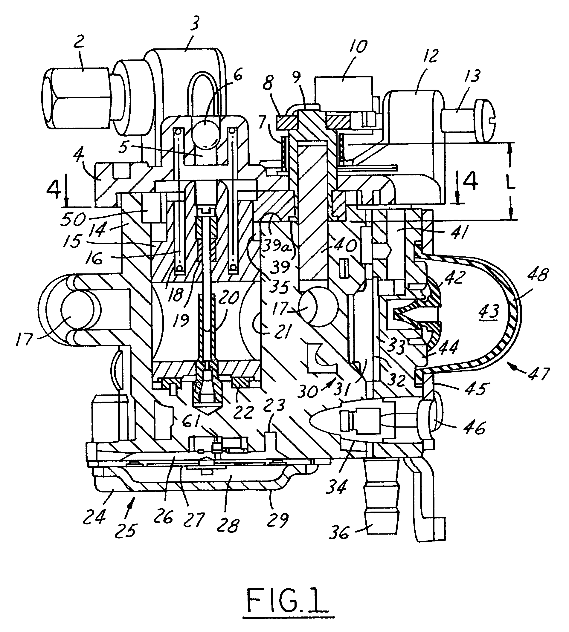
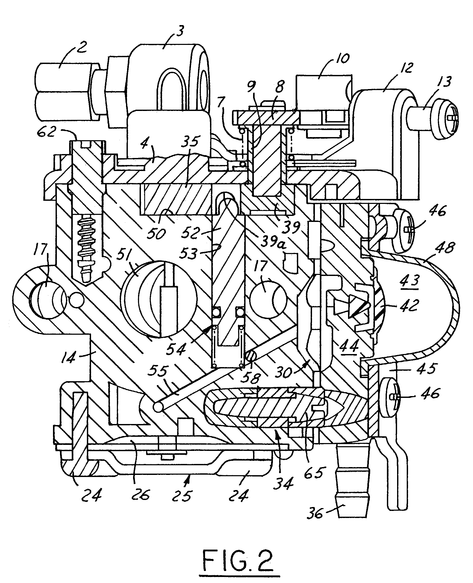
[0028]As shown in FIGS. 1 and 2, a carburetor has a carburetor body 14 with an air intake passage 51 extending through the body. In assembly, the carburetor is disposed between an air cleaner, not shown, and a wall surrounding an intake port of the engine, preferably with an insulating plate between them. The body 14 may be fastened to the engine by a pair bolts extending through mounting holes 17. A rotary throttle valve 15 having a throttle hole 18 is rotatably and axially slidably received in a cylindrical valve chamber 21 that is formed perpendicular to the air intake passage 51 of the carburetor body 14.

[0029]An annular cam 22 is provided at the bottom of the valve chamber 21 and has a pair of peripheral cam surfaces 22a (FIG. 7) with a height that varies along the circumferential extent of the cam surfaces 22a, as shown in FIGS. 6 and 7. The cam 22 has a pair of pins 22b which are inserted into pin holes in the valve chamber 21. Rod-like followers 15a carried by the throttle v...


PUM

PropertyMeasurementUnit
heightaaaaaaaaaa
axial displacementaaaaaaaaaa
shapeaaaaaaaaaa

Abstract

A rotary throttle valve carburetor includes an air intake passage and a throttle valve bore formed in a carburetor body, a cam disposed in the throttle valve bore, and a throttle valve disposed in the throttle valve bore so that one end engages the cam and the other end is accessible from outside the throttle valve bore for operable connection to a throttle valve lever. The carburetor may also have a cable holder with a receiving cylinder for an outer tube of a throttle valve lever cable, an insert port for an inner wire of the cable and a slit between the receiving cylinder and insert port. The slit is smaller than an end of the inner wire to prevent that end from passing through the slit. The carburetor may further include a tamper resistant fuel adjustment bolt including an anti-turning body keyed to the carburetor body and splined to the adjustment bolt after calibration of the carburetor to prevent inadvertent rotation, or user tampering with the calibrated setting.

Description

REFERENCE TO RELATED APPLICATIONS[0001]Applicant claims priority of Japanese Patent Applications, Ser. No. 2002-161,710 filed Jun. 3, 2002; Ser. No. 2002-171,548 filed Jun. 12, 2002; and Ser. No. 2002-308,510 filed Oct. 23, 2002.FIELD OF THE INVENTION[0002]The present invention relates generally to a carburetor, and more particularly to a rotary throttle valve carburetor.BACKGROUND OF THE INVENTION[0003]In the conventional rotary throttle valve carburetor, moving the rotary throttle valve via a link or lever mechanism, an excessive or undesirably high force may be required to operate the throttle, which can be a limiting requirement in design. Further, a cam for causing the rotary throttle valve to move vertically is also provided between the carburetor body and a lever that actuates the rotary throttle valve. This limits the design freedom as far as shape of the cam and the type of mateiral that can be used.[0004]In a fuel adjustment needle valve of a carburetor proposed in Japanes...

Claims


Application Information

Patent Timeline
Patent Type & Authority Patents(United States)
IPC IPC(8): F02M9/08
CPCF02M9/085
Inventor TOBINAI, TERUHIKO
Owner NIPPON WALBRO KK
Why Eureka
Try Eureka