Composite Interference Screws and Drivers

Active Publication Date: 2012-07-12
SMITH & NEPHEW INC
View PDF5 Cites 47 Cited by
  • Summary
  • Abstract
  • Description
  • Claims
  • Application Information

AI Technical Summary

Problems solved by technology

In many cases, ligaments are torn or ruptured as the result of an accident.
However, the interference screw itself generally takes up a substantial amount of space within the bone tunnel, which can limit the surface area contact established between the graft ligament and the side wall of the bone tunnel.
This in turn limits the region of bone-to-ligament in-growth, and hence can affect the strength of the joinder.
However, these absorbable interference screws st

Method used


Image

  • Composite Interference Screws and Drivers
  • Composite Interference Screws and Drivers
  • Composite Interference Screws and Drivers

Examples


Embodiment Construction

[0050]The following description of the preferred embodiment(s) is merely exemplary in nature and is in no way intended to limit the disclosure, its application, or uses.

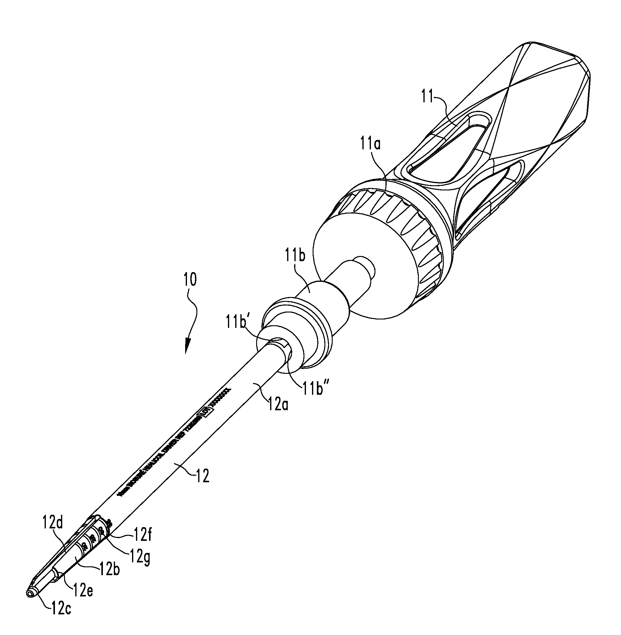
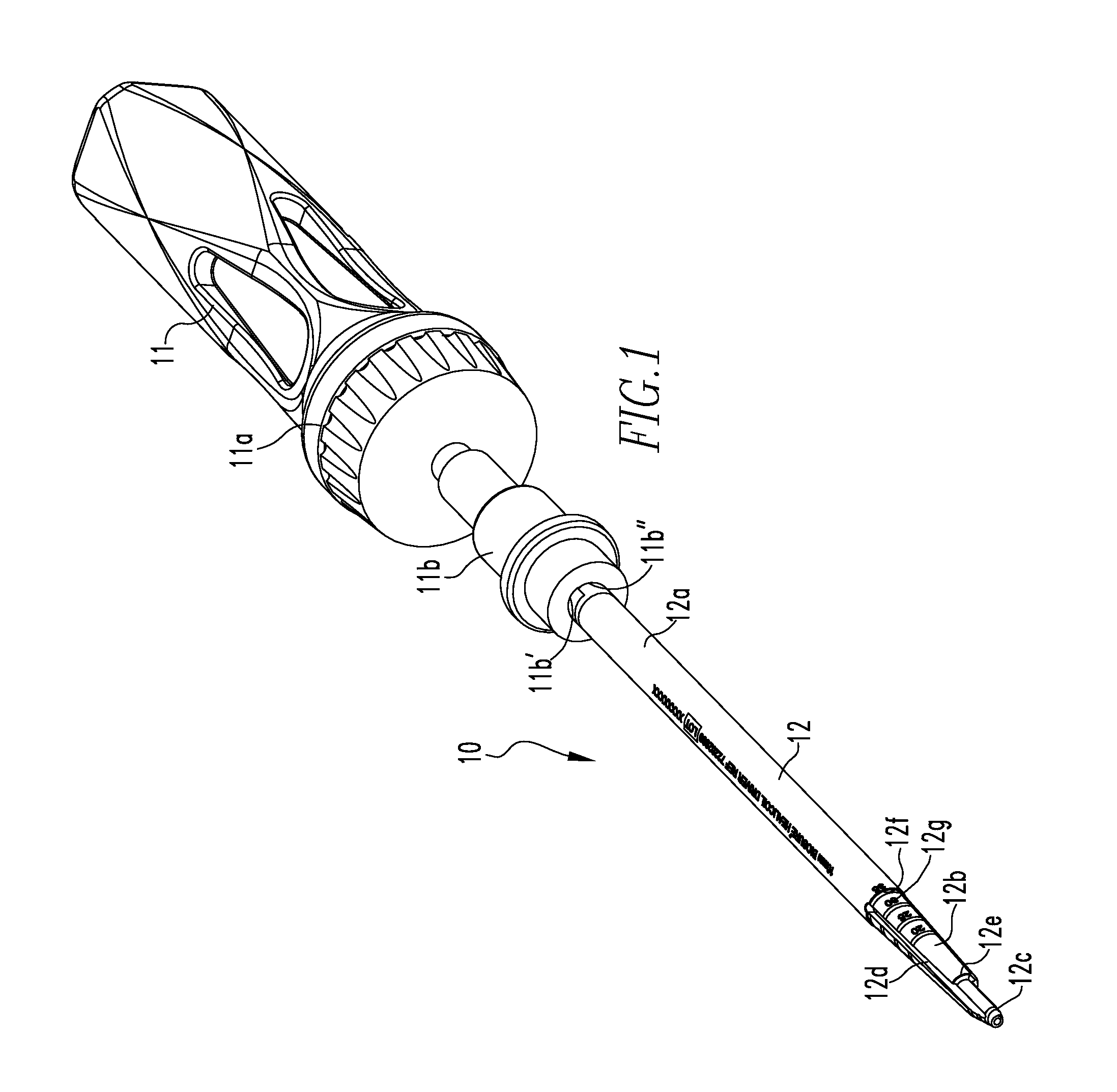
[0051]FIG. 1 shows a first embodiment of the delivery device 10 of the present disclosure. The device 10 includes a handle assembly 11 and a shaft 12 coupled to the handle assembly 11. The handle assembly 11 includes a handle 11a and a connector 11b coupled to the handle 11a. The connector 11b has a channel 11b′ and an opening 11b″ to the channel 11b′. The opening 11b″ is in the shape of a “D”. A proximal end 12a of the shaft 12 is disposed within the channel 11b′.

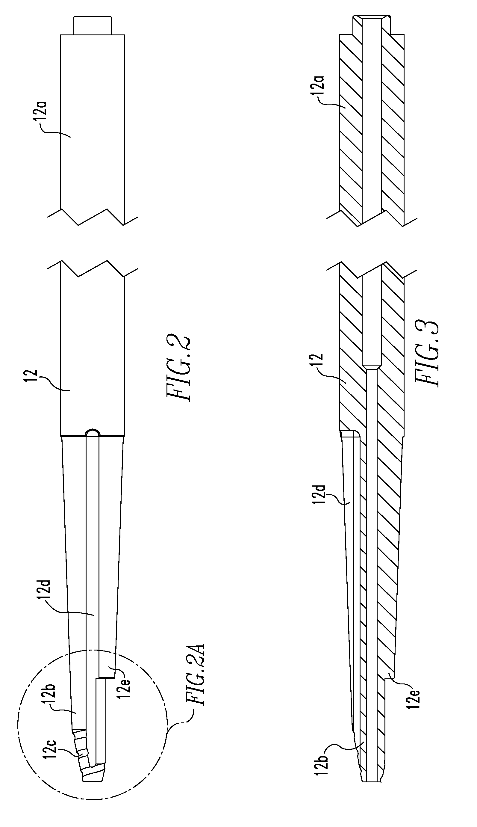
[0052]FIGS. 2, 2A, and 3-4 show the shaft 12. The shaft 12 includes a proximal end 12a and a distal end 12b. The proximal end 12a is in the shape of a “D” to match the shape of the opening 11b″. The distal end 12b includes threads 12c, grooves 12d, and a depth stop 12e. The grooves 12d extend a partial length of the shaft 12 and intersect the threads 12c. ...


PUM


Abstract

The present disclosure relates to a delivery device and screw combination. The combination includes a delivery device comprising a handle and a shaft coupled to the handle, the shaft including a proximal end, a distal end, a non-circular cannulation, and markings along a length of the shaft; an interference screw coupled to the delivery device comprising a proximal end and a distal end, the screw including threads extending in an open helical form from the proximal end to the distal end, a suture bridge located at a distal end of the screw and housed within a slot of the delivery device shaft, and a plurality of runners extending longitudinally along an interior of the screw, the runners housed within grooves of the delivery device shaft; and a suture disposed around the suture bridge, ends of the suture extending through the cannulation of the delivery device shaft.

Description

CROSS-REFERENCE TO RELATED APPLICATIONS[0001]This application is a continuation-in-part patent application claiming priority to U.S. Patent Application Ser. No. 61 / 451644, filed Mar. 11, 2011, U.S. Patent Application Ser. No. 61 / 451731, filed on Mar. 11, 2011, U.S. Patent Application Ser. No. 61 / 451736, filed Mar. 11, 2011, U.S. Patent Application Ser. No. 61 / 451743, filed on Mar. 11, 2011, and Ser. No. 13 / 044777, filed on Mar. 10, 2011, which claims priority to U.S. Patent Application Ser. No. 61 / 312291, filed on Mar. 10, 2010, U.S. Patent Application Ser. No. 61 / 334808, filed on May 14, 2010, and U.S. Patent Application Ser. No. 61 / 359080, filed on Jun. 28, 2010, the disclosures of which are incorporated herein by reference in their entireties.BACKGROUND[0002]1. Field of Technology[0003]The present disclosure relates to medical apparatuses and procedures in general, and more particularly to medical apparatuses and procedures for reconstructing a ligament.[0004]2. Related Art[0005]...

Claims


Application Information

Patent Timeline
IPC IPC(8): A61B17/56
CPCA61B17/0401A61B2017/0409A61B2017/0441A61F2/0805A61F2/0811A61B2019/462A61F2002/0858A61F2002/0888A61F2250/0097A61B2017/0458A61F2002/0841A61B17/864A61B17/8645A61B17/869A61B17/888A61B17/8888A61B2017/044A61F2210/0004A61B2090/062A61B17/0466A61B17/8875A61F2002/087
Inventor HOUSMAN, MARK EDWINVINCUILLA, PAUL STEVENCASHMORE, PETER JAMESBLOUGH, REBECCA ANNFAN, WEI LI
Owner SMITH & NEPHEW INC
Why Eureka
Try Eureka