Porous interbody fusion device having integrated polyaxial locking interference screws

a technology of interbody fusion and interferon, which is applied in the field of spinal implant devices, can solve the problems of loss of proper anatomical spacing between the end plates of the opposing vertebrae, considerable neurological impairment, and general failure of the intervertebral disc cartilag

Inactive Publication Date: 2009-11-24
WARSAW ORTHOPEDIC INC
View PDF7 Cites 42 Cited by
  • Summary
  • Abstract
  • Description
  • Claims
  • Application Information

AI Technical Summary

Benefits of technology

[0029]Once the spacer of the present invention is properly positioned, the surgeon inserts the screws through the holes at the desired angle and drives it into the adjacent bone. Complete insertion of the crew causes the coupling member (the collet) to slide into the tapered hole of the spacer and to lock therein, independent of the angulation of the screw (within a range of angles). This secures the spacer implant in the appropriate position. The ability to angulate the screw is a significant advantage. The ability to angulate the screws while simultaneously having the heads of the screws locked to the spacer is the principle advantage of the present invention, which is described in particular preferred embodiments hereinafter, with reference to the included Figures.

Problems solved by technology

Failure of the intervertebral disc cartilage generally includes a loss of proper anatomical spacing between the end plates of the opposing vertebral bodies.
This loss of height may simply destabilize the spine, or, in severe cases, it may cause considerable neurological impairment as the nerve roots are compressed by the converging lateral extensions of the bones (e.g. in the facet joint).
Some of these implant devices are only suitable for one direction of approach to the spine.
The measuring tool is, however, not used to distract the space.
Failure to properly cut the space, or structural failure of the graft and / or bone material, will prevent removal of the guides, and further rotation of the shaft will drive the allograft further than clinically desired (risking paralysis and / or damage to surrounding vessels).
Referring now to the implant device itself, the substantial drawbacks of cage devices, including, but not limited to: 1. their failure to induce or accept robust ingrowth of bone for the development of a fusion; and 2. their susceptibility to sudden rotational instability, have led to their decreased usage.
The proper porosity of the allograft bone makes it a superior fusion material, however, simple compression between the adjacent bones (often aided by the tension band of the remaining annulus material) is often not deemed sufficient to prevent dislocation of the implanted ring.
While effective, this stabilization technique does not entirely prevent movement of the allograft material, and thus does not prevent fusion inhibiting translating events.

Method used


Image

  • Porous interbody fusion device having integrated polyaxial locking interference screws
  • Porous interbody fusion device having integrated polyaxial locking interference screws
  • Porous interbody fusion device having integrated polyaxial locking interference screws

Examples


Embodiment Construction

[0035]While the present invention will be described more fully hereinafter with reference to the accompanying drawings, in which particular embodiments and methods of fabrication are shown, it is to be understood at the outset that persons skilled in the art may modify the invention herein described while achieving the functions and results of this invention. Accordingly, the descriptions that follow are to be understood as illustrative and exemplary of specific structures, aspects and features within the broad scope of the present invention and not as limiting of such broad scope. Like numbers refer to similar features of like elements throughout.

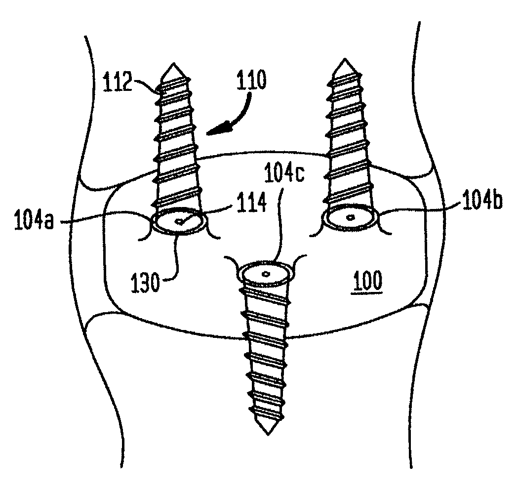
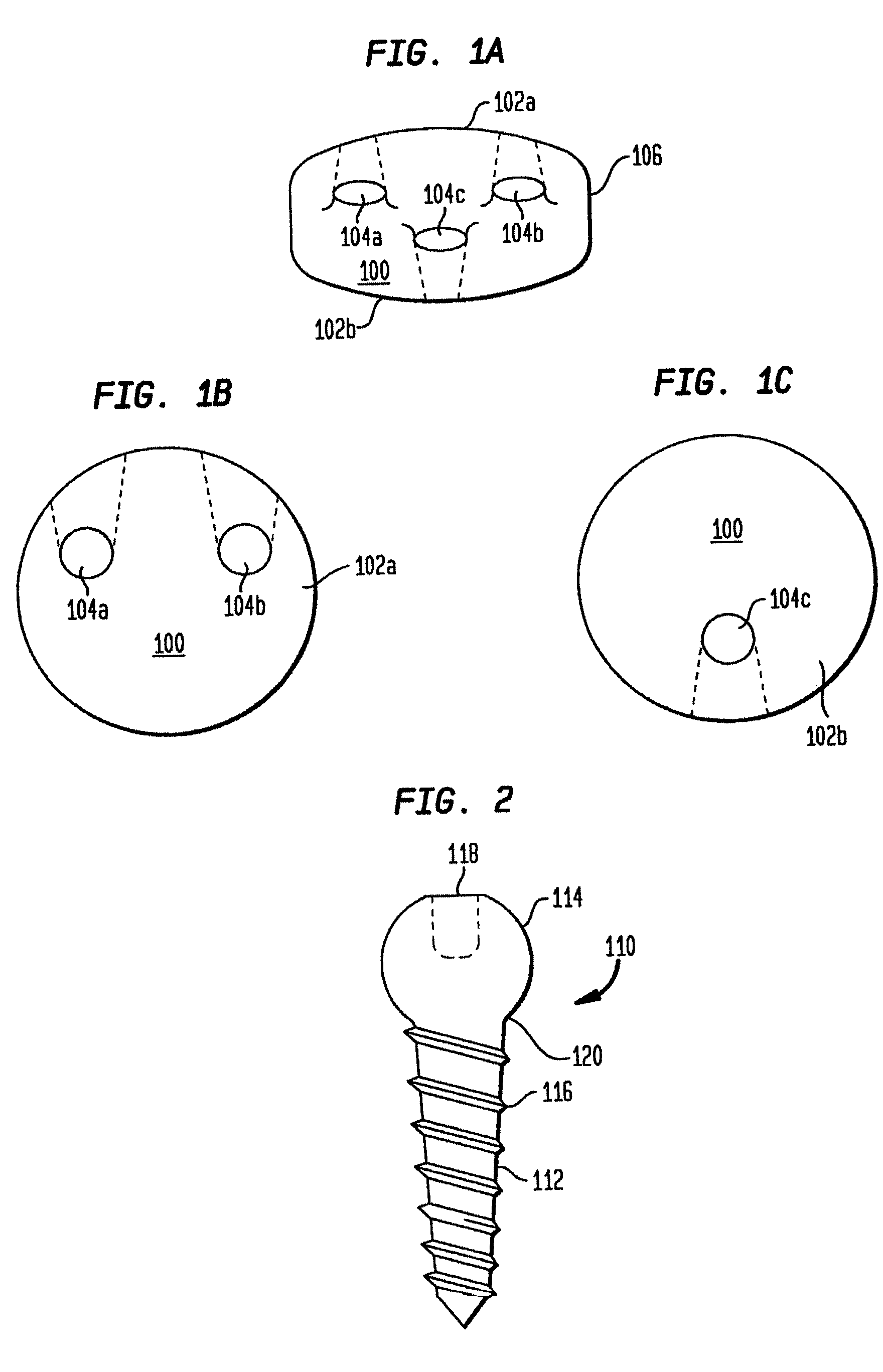
[0036]Referring now to FIGS. 1a-c, a porous metal intervertebral spacer device 100 is provided in side, top and bottom views, respectively. The device is disc shaped, having a diameter that is approximately eighty percent of the diameter of the end plates of the adjacent vertebral bodies. This permits a greater portion of the end plates of...


PUM


Abstract

A porous metal intervertebral spacer having at least one angled through hole extending from the side of the implant to a surface which interfaces with a vertebral body end plate such that an interference screw may be driven through the implant and into the bone, thereby securing the implant from undesired motion. In particular, the through holes are tapered to receive a screw and coupling element therethrough such that once fully seated, the screw is locked to the implant by virtue of a coupling element-through hole mutually tapered nesting. The head of the screw is round, as is the interior of the coupling element, thereby allowing the screw to be inserted at various angles relative to the hole without interfering with the proper seating of the coupling element in the through hole.

Description

CROSS REFERENCE TO RELATED APPLICATION[0001]This application is a continuation application of U.S. patent application Ser. No. 09 / 844,904, entitled “Porous Interbody Fusion Device Having Integrated Polyaxial Locking Interference Screws”, filed Apr. 27, 2001, now U.S. Pat. No. 6,558,387, which is a continuation-in-part of Reissue application Ser. No. 09 / 774,915, entitled “A Polyaxial Pedicle Screw Having a Threaded and Tapered Compression Locking Mechanism”, filed Jan. 30, 2001, now Reissue Pat. No. RE37,665.BACKGROUND OF THE INVENTION[0002]1. Field of the Invention[0003]This invention relates generally to a spinal implant device for implantation into the intervertebral space between adjacent vertebral bones to potentiate fusion, and more particularly to an implantable device having superior stability provided by polyaxial locking interference screws.[0004]2. Description of the Prior Art[0005]The bones and connective tissue of an adult human spinal column consists of more than twenty...

Claims


Application Information

Patent Timeline
Patent Type & Authority Patents(United States)
IPC IPC(8): A61F2/44A61B17/70A61B17/86A61F2/00A61F2/30A61F2/46
CPCA61B17/7032A61B17/7037A61B17/7059A61B17/8605A61F2/30744A61F2/34A61F2/442A61F2/4611A61F2310/00023A61B17/809A61B17/86A61B17/8625A61F2002/3021A61F2002/30329A61F2002/30332A61F2002/30378A61F2002/30497A61F2002/30594A61F2002/30787A61F2002/3401A61F2002/4627A61F2002/4628A61F2220/0025A61F2220/0033A61F2230/0067A61F2310/00011A61F2310/00017A61B17/7034A61F2002/30495
Inventor ERRICO, THOMAS J.RALPH, JAMES D.ERRICO, JOSEPH P.
Owner WARSAW ORTHOPEDIC INC
Why Eureka
Try Eureka