
Facet interference screw

a technology of interference screw and facet, which is applied in the field of facet interference screw, can solve the problems of degenerated facet joint pain and patient pain, and achieve the effect of facilitating damping the firs

Active Publication Date: 2011-01-06
DEPUY SYNTHES PROD INC
View PDF104 Cites 67 Cited by
  • Summary
  • Abstract
  • Description
  • Claims
  • Application Information

AI Technical Summary

Benefits of technology

[0007]In another preferred embodiment of the facet interference screw, a damping component may be inserted between the inner surfaces of the first and second components to facilitate damping of the first and second components with respect to one another. The damping component may be in the form of a two-piece damping component including an upper damping component having an outer surface for contacting the inner surface of the first component and an inner surface. The damping component may also include a lower damping component having an outer surface for contacting the inner surface o

Problems solved by technology

Degenerated facet joints are often painful as a result of, for example, wear between two arthritic articulating surfaces that surround the synovial joint capsule.
Inflammatory reactions may occur when the cartilaginous surfaces of the facets become degraded or fissured, thereby leading to direct bone-on-bone contact and resulting in pain.
Over distraction of the surrounding joint capsules may also cause pain to the patient.

Method used


Image

  • Facet interference screw
  • Facet interference screw
  • Facet interference screw

Examples


Embodiment Construction

[0033]Certain terminology is used in the following description for convenience only and is not limiting. The words “right”, “left”, “top” and “bottom” designate directions in the drawings to which reference is made. The words “inwardly” and “outwardly” refer to directions toward and away from, respectively, the geometric center of the facet interference screw and designated parts thereof. The words, “anterior”, “posterior”, “superior”, “inferior”, “lateral”, “sagittal”, “axial”, “coronal” and related words and / or phrases designate preferred positions and orientations in the human body to which reference is made and are not meant to be limiting. The terminology includes the above-listed words, derivatives thereof and words of similar import.

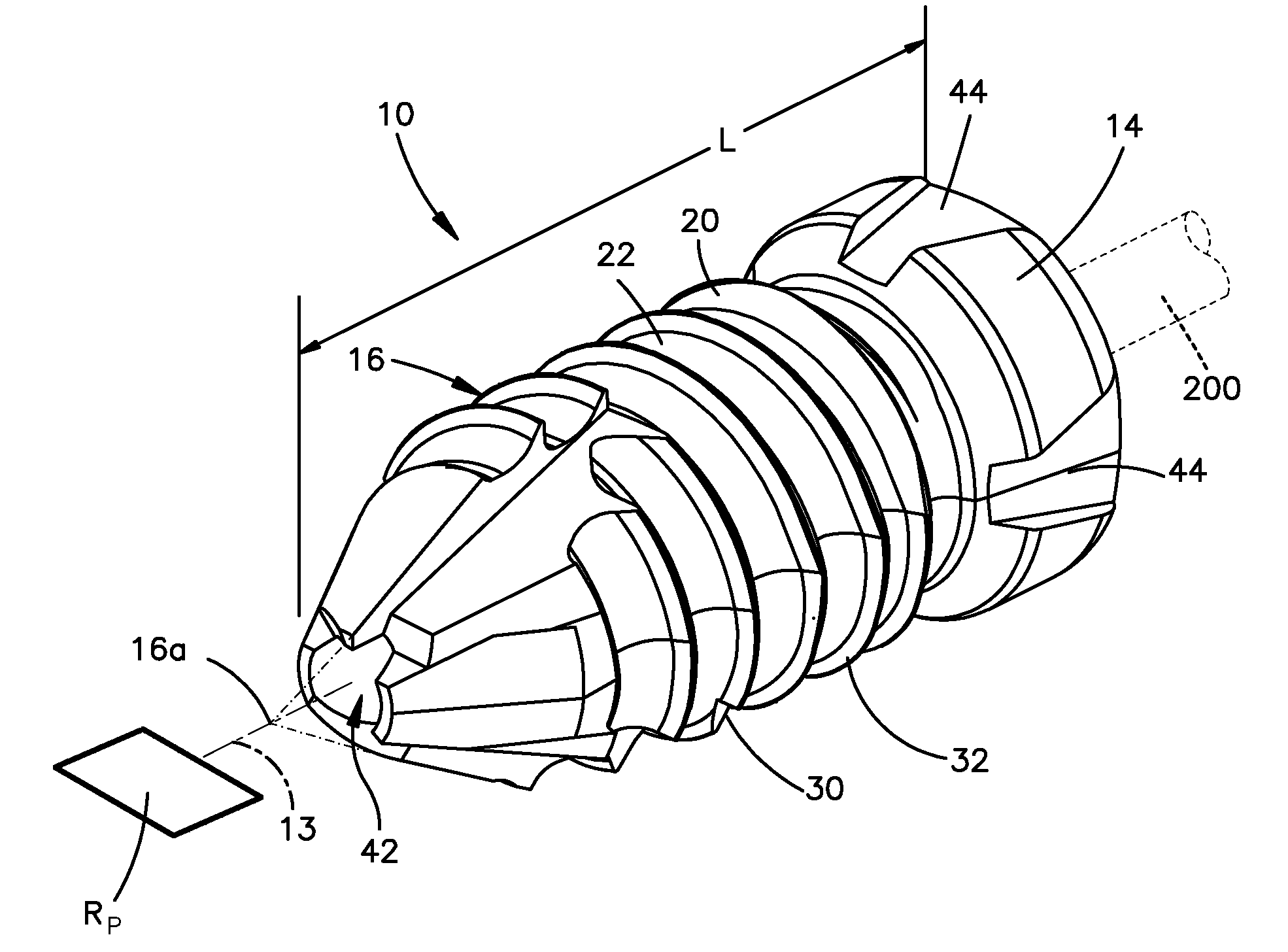
[0034]Certain exemplary embodiments of the invention will now be described with reference to the drawings. Preferred embodiments of the present invention are directed to (i) first, second and third preferred embodiments of a facet interference scr...


PUM

PropertyMeasurementUnit
Thermoplasticityaaaaaaaaaa

Abstract

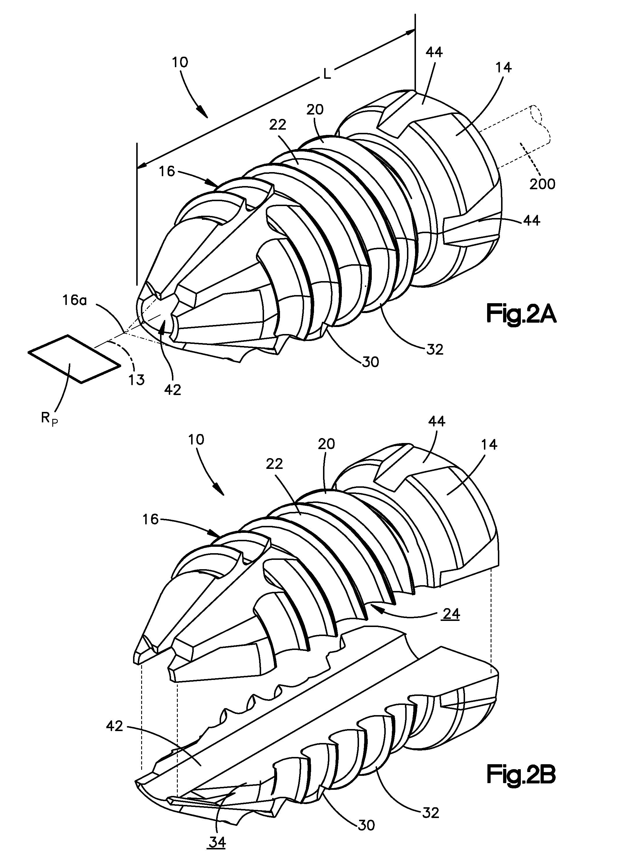
A facet interference screw (10) for insertion between the facet joints of adjacent superior and inferior vertebrae includes an externally threaded shaft portion and a head. The facet interference screw is preferably split into first (20) and second (30) components, each including an outer, semicircular externally threaded surface (22, 32) so that when coupled together the semicircular externally threaded surfaces form the externally threaded shaft portion. The inner surfaces (24, 34) of the first and second components may include curved contacting surfaces so that when inserted, the first component is movable with respect to the second component. Alternatively, the screw may include a damping component (60a′) between the inner surfaces of the first and second components to facilitate damping of the first and second components with respect to one another. The damping component preferably also facilitates articulated motion of the first and second components.

Description

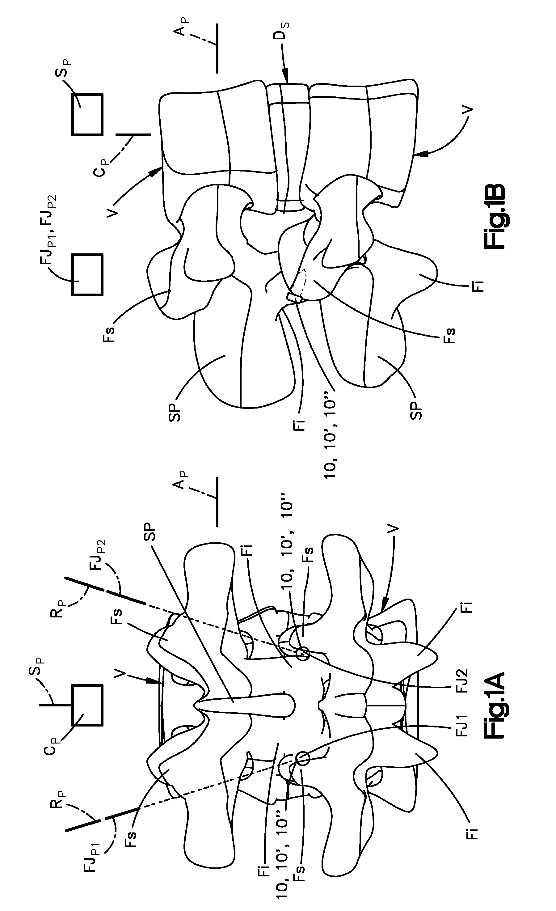
CROSS-REFERENCE TO RELATED APPLICATIONS[0001]This application claims the benefit of U.S. Provisional Application No. 61 / 034,295, filed on Mar. 6, 2008, entitled “FACET INTERFERENCE SCREW,” the contents of which is incorporated in its entirety by reference herein.BACKGROUND OF THE INVENTION[0002]The facet joint is an articulating joint of a spinal motion segment that can degenerate during aging, trauma, typical use and other factors. The facet joints in various regions of the spine are oriented in different planes, for example, the lumbar facet joints are generally located in the sagittal plane SP, the thoracic facet joints are generally oriented in the coronal plane CP and the cervical facet joints are generally oriented in the axial or transverse plane AP (FIGS. 1 and 2). These orientations facilitate different types of motion in the respective regions of the spine.[0003]Degenerated facet joints are often painful as a result of, for example, wear between two arthritic articulating ...

Claims


Application Information

Patent Timeline
IPC IPC(8): A61B17/70A61B17/88
CPCA61B17/7064A61F2310/00886A61B17/866A61B17/8685A61B17/8883A61B17/8891A61F2/4405A61F2/4425A61F2002/30563A61F2002/30617A61F2002/30672A61F2002/4677A61F2250/0059A61F2250/0097A61F2310/00017A61F2310/00023A61F2310/00407A61F2310/00604A61F2310/00634A61F2310/0073A61F2310/00748A61F2310/00754A61F2310/00796A61F2310/00856A61F2310/0088A61B17/862
Inventor LECHMANN, BEATPAVLOV, PAUL W.ZURSCHMIEDE, SILAS
Owner DEPUY SYNTHES PROD INC
Learn More