
Bag zipper lockable with tethered cable lock

Inactive Publication Date: 2012-07-19
NOBLE SECURITY
View PDF5 Cites 7 Cited by
  • Summary
  • Abstract
  • Description
  • Claims
  • Application Information

AI Technical Summary

Benefits of technology

[0007]It is an object of the present invention to avoid the drawbacks o

Problems solved by technology

But, of course, the padlock lock would just close the carrying bag, but would not prevent pilferage of the entire bag.

Method used


Image

  • Bag zipper lockable with tethered cable lock
  • Bag zipper lockable with tethered cable lock
  • Bag zipper lockable with tethered cable lock

Examples


Embodiment Construction

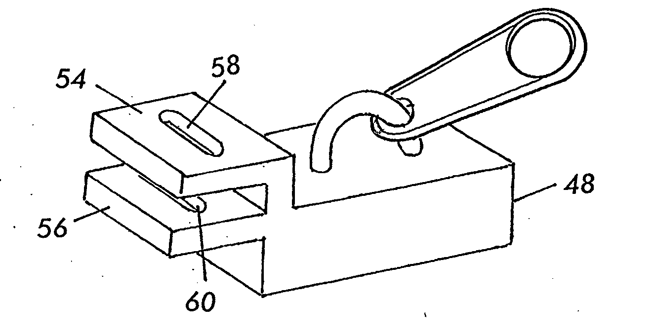
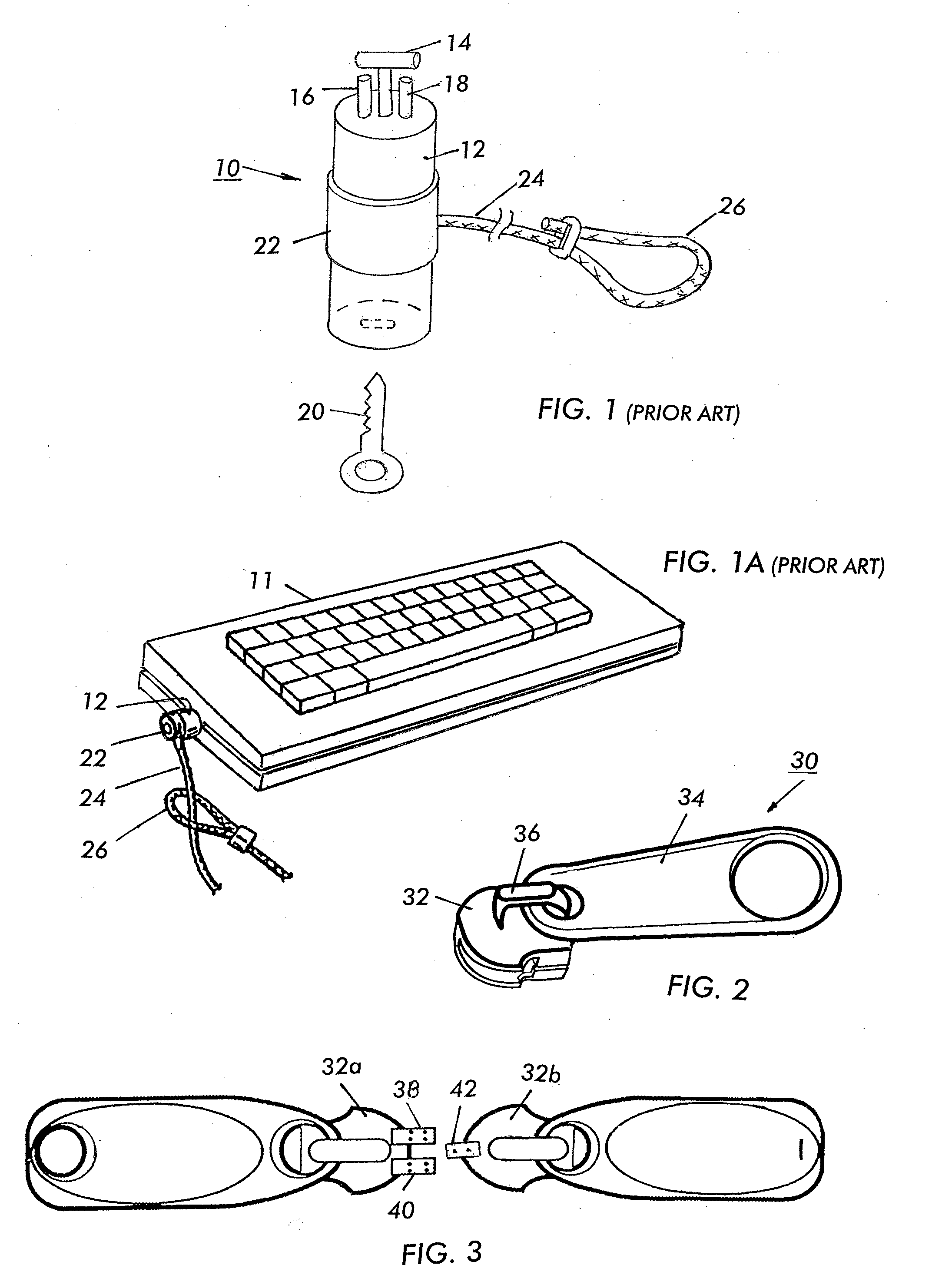
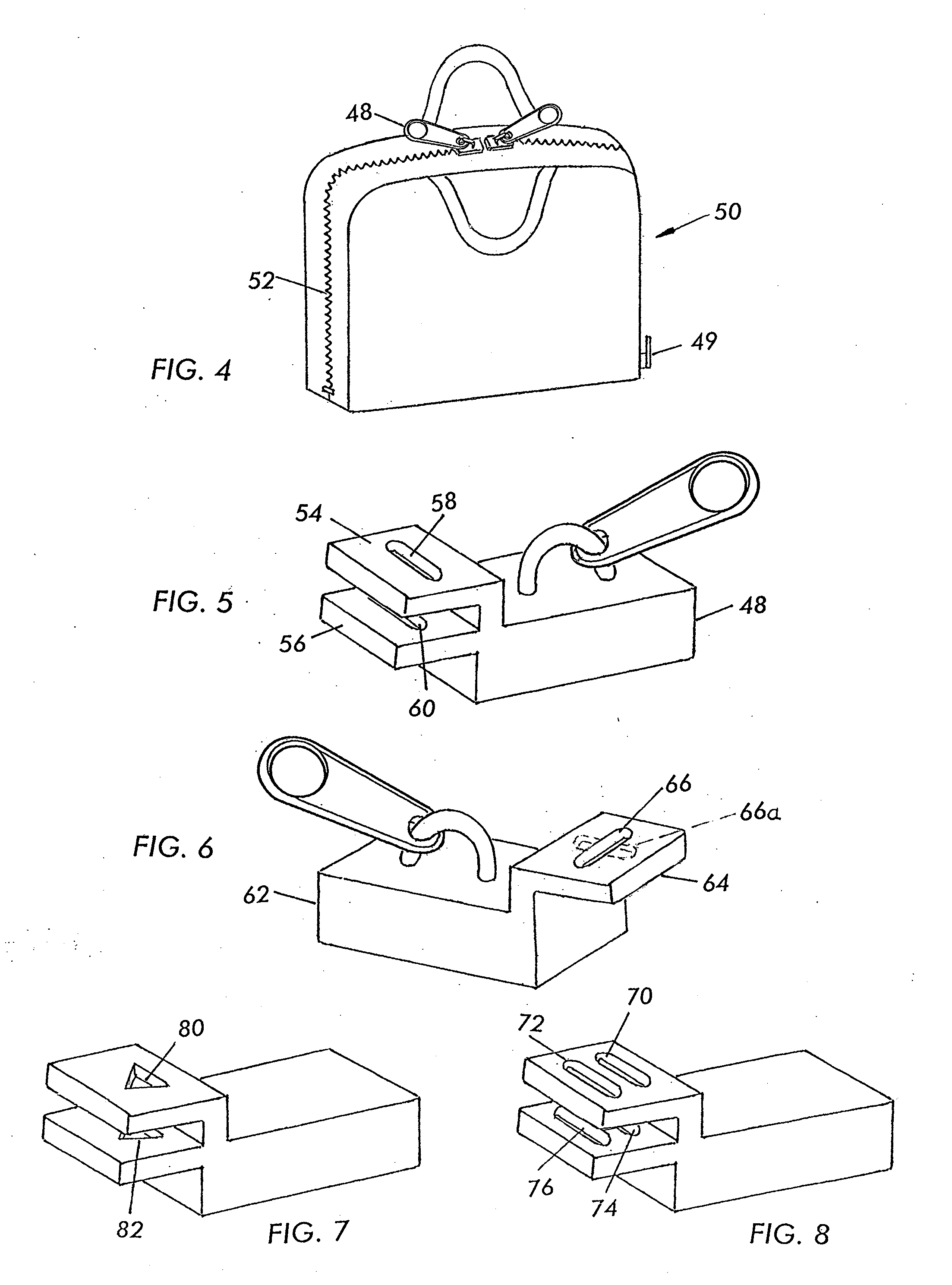
[0021]The standardized computer lock 10 of FIG. 1 has a cylindrical body 12 with a rotatable T-bar locking element 14 with two pins 16, 18 that prevent rotation of the lock body 12 in the 3×7 mm security lock. When the key 20 is utilized to rotate the T-bar 14 in a rectangular 3×7 mm security slot, the lock 10 becomes attached to the particular piece of equipment, for example, a computer or keyboard 11, in well known manner. The lock 10 has a sleeve 22 that supports a long cable 24 with a loop 26 at the end, which is large enough to slip the lock therethrough. This type of a lock is described in great detail in the aforementioned U.S. Pat. Nos. 7,249,474 and 7,100,404 patents the contents of which have been incorporated by reference. The T-bar locking element can be a scissors action or other type of locking element as described, for example, in the U.S. Pat. No. 7,100,404 patent.

[0022]The zipper slider 30 of FIG. 2 has a slider 32, and a pull 34 that is attached to the slider via a...


PUM


Abstract

A bag which has a zipper which is closable over an interior space of the bag using a zipper slider. The zipper slider has a pull and a first locking tab which juts forwardly from one end of the zipper slider and defines therein a first locking slot sized to receive a locking element of a lock. A second locking tab defines a second locking slot with the second locking slot also being shaped to receive the locking element. The first and second locking tabs are configured to be selectively overlapped or aligned so as to register their locking slots, whereby upon passage of the locking element through both locking slots, access to the interior space of the bag is prevented. The locking element can be connected to a cable with a loop to tether the bag to an immovable object.

Description

CROSS REFERENCE TO RELATED APPLICATIONS[0001]The present application claims the benefit of U.S. Provisional Patent Application No. 61 / 432,773 filed on Jan. 14, 2011; which is incorporated herein by reference in its entirety.BACKGROUND OF THE INVENTION[0002]The present invention relates to a carrying bags, including computer bags and, more particularly, to zipper lock mechanisms which are suitable for being locked with a T-bar style lock that also incorporates a cable which allows the carrying bag to be tethered to an immovable object, such as to a chair or a desk.[0003]Computer security locks have become popular, as well as standardized. One of those locks which has been made famous by Kensington, has a cylindrical body with a T-bar locking element which measures about 3×7 mm and fits a standardized slot of similar measurement that has been formed in computer equipment, such as laptops, displays, and other electronic devices. U.S. Pat. Nos. 7,249,474 and 7,100,404 describe such stan...

Claims


Application Information

Patent Timeline
IPC IPC(8): A44B19/26
CPCA44B19/301A45C3/02Y10T24/2507A45C13/20E05B73/0005A45C13/103
Inventor AVGANIM, MEIR
Owner NOBLE SECURITY
Learn More