Interactive Presentation System

a presentation system and interactive technology, applied in the field of interactive presentation systems, can solve problems such as inability to reach difficult operations at the upper part of the screen, and presenters may not be able to reach and point the menu screen in the image projection area

Active Publication Date: 2012-07-19
PANASONIC INTELLECTUAL PROPERTY MANAGEMENT CO LTD
View PDF29 Cites 26 Cited by
  • Summary
  • Abstract
  • Description
  • Claims
  • Application Information

AI Technical Summary

Benefits of technology

[0026]An advantageous effect obtained with the interactive presentation system of the present invention configured as described above is that, a pointed position can be identified by the system, by having boundary coordinate settings for an operation area to be set such that an operation area is formed at an arbitrary position outside an image projection area, and thereby a presenter can point the arbitrary position in the operation area to execute an operation command associated to the position. As a result, by setting boundary positions in the initialization stage, even when the image projection area is a big screen, there will not be any areas that cannot be reached and pointed by the presenter. Furthermore, even if the image projection area is not a big screen, a presenter of shorter stature, such as a child, may not be able to reach and point some areas, but such a problem can be solved by setting boundary positions at a low level in the initialization stage.

Problems solved by technology

However, when performing an interactive operation with a conventional interactive presentation system by pointing to a menu screen in an image projection area, if the image projection area is a large screen, areas that cannot be reached and pointed by a presenter may exist on the screen.
In such a case, operations become particularly difficult at an upper part of the screen.
Furthermore, even when the image projection area is not a big screen, a presenter may not be able to reach and point the menu screen on the image projection area when the presenter is a child or person of shorter stature.
As a result, a problem arises where the area for displaying the contents of the presentation becomes small.

Method used


Image

  • Interactive Presentation System
  • Interactive Presentation System
  • Interactive Presentation System

Examples


embodiment 1

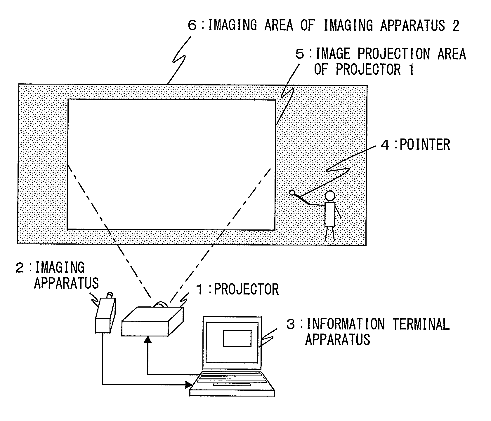
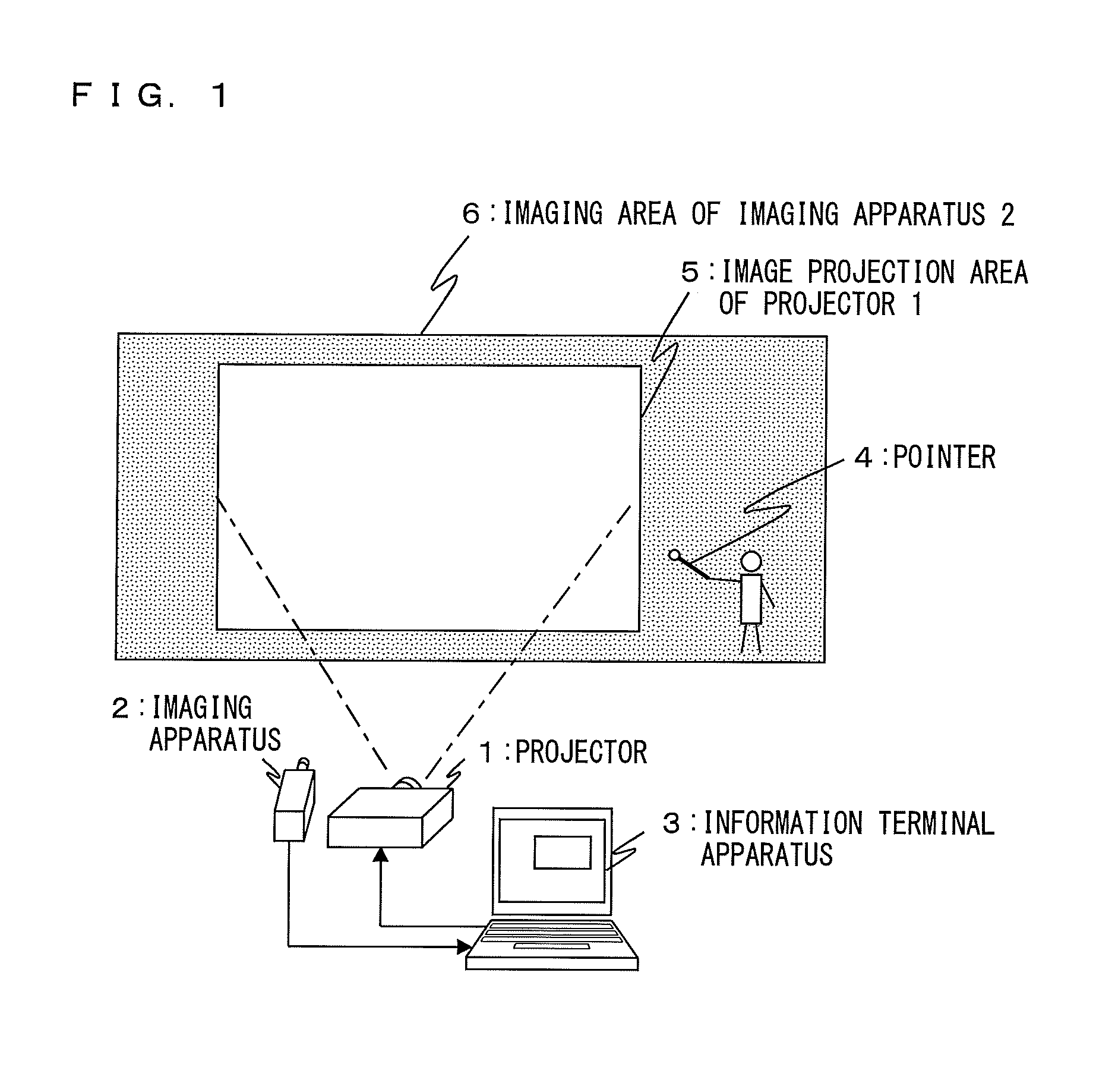
[0047]FIG. 1 shows a configuration of an interactive presentation system according to embodiment 1 of the present invention.

[0048]With regard to reference characters in FIG. 1, element 1 represents a projector capable of enlarging and projecting an image, element 2 represents an imaging apparatus capable of taking an image of an imaging area, element 3 represents an information terminal apparatus such as a personal computer or the like, and element 4 represents a transmission device such as a pointer. Furthermore, element 5 represents an image projection area for receiving a projection from the projector 1, and element 6 represents an imaging area of the imaging apparatus 2.

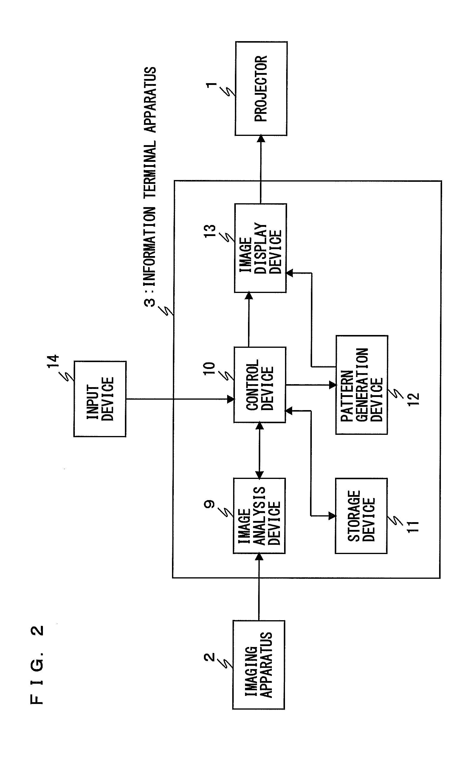
[0049]FIG. 2 shows an internal configuration of the information terminal apparatus 3. With regard to reference characters in FIG. 2, element 9 represents an image analysis device (image analyzer) configured to analyze image data transmitted from the imaging apparatus 2, element 11 represents a storage device conf...

embodiment 2

[0065]FIG. 8 is a flowchart for describing an operation of an interactive presentation system according to embodiment 2 of the present invention.

[0066]First, the presenter issues an initialization command to the information terminal apparatus 3 by using the input device 14 in order to ascertain where the image projection area 5 for receiving a projection from the projector 1 exists in the imaging area 6 of the imaging apparatus 2 (step S10). The control device 10 that has received the initialization command at step S10 causes the pattern generation device 12 to project initialization patterns 7 shown in FIG. 9 from the projector 1 via the image display device 13 (step S11). In FIG. 9, an example is shown in which four cross-shaped characters are disposed as the initialization patterns 7 at four corners of the image projection area 5 of the projector 1. It is needless to say that similar advantageous effects can also be obtained when the number of such characters is not four, or when...

embodiment 3

[0089]FIG. 14 is a flowchart for describing an operation of an interactive presentation system according to embodiment 3 of the present invention, and FIG. 15 shows one example of a boundary area pattern 21 of a pattern generation device according to embodiment 3. With regard to the reference characters in FIG. 15, element 21 represents a boundary area pattern displayed on the information terminal apparatus 3, element 22 represents a boundary area obtained when the boundary area pattern 21 is set, and element 23 represents a display coordinate for uniquely determining a position for displaying the boundary area pattern 21 on a taken image.

[0090]An example will be described by using the flowchart in FIG. 14 for describing an operation, and in this example, a square illustrated by a dashed line in FIG. 15 is set as the boundary area 22, and the area within the boundary area 22 is set as an operation area.

[0091]First, in order to specify the boundary area 22 by using the information te...


PUM


Abstract

An interactive presentation system includes: an imaging device; an image analyzer that calculates information regarding a pointed position by using captured-image data; a controller that receives the information and operates based on an input from an input device; a storage device controlled by the controller to store the information; a pattern generator controlled by the controller to generate a pattern image; an image display device that receives an output from the pattern generator; and a projector that enlarges and projects an output from the image display device. Upon initialization based on the input from the input device, the controller defines a pointed position as a boundary position of a command, assigns the command to an area demarcated by the boundary position, and stores the boundary position in the storage device. After initialization, the controller compares a pointed position and the boundary position and executes the command associated to the information.

Description

BACKGROUND OF THE INVENTION[0001]1. Field of the Invention[0002]The present invention relates to interactive presentation systems that use projectors.[0003]2. Description of the Background Art[0004]In recent years, projectors are widely used as apparatuses for presentations. Screens displayed on information terminal apparatuses can be enlarged and projected on image projection areas by simply connecting image output terminals of the information terminal apparatuses to projectors by using, for example, VGA cables or the like. Then, operations such as switching screens and turning a page forward can be performed on the information terminal apparatuses by using operational remote controls. However, recently, there has been a demand for presentation apparatuses allowing more interactive and diverse operations. In systems (e.g., Patent Literature 1) which have been developed in order to respond to such a demand, operation commands are assigned to positions on a menu screen displayed in a...

Claims


Application Information

Patent Timeline
Patent Type & Authority Applications(United States)
IPC IPC(8): G09G5/08G06F3/0346
CPCG06F3/005H04N9/3185G06F3/0346G06F3/038H04N9/3194
Inventor TAKAMATSU, KEITSURUDA, KENSHI
Owner PANASONIC INTELLECTUAL PROPERTY MANAGEMENT CO LTD
Why Eureka
Try Eureka