Light guide module of scanning apparatus

Inactive Publication Date: 2012-07-19
PRIMAX ELECTRONICS LTD
View PDF5 Cites 5 Cited by
  • Summary
  • Abstract
  • Description
  • Claims
  • Application Information

AI Technical Summary

Benefits of technology

[0010]The present invention provides a light guide module of a scanning apparatus for enhancing the scanning quality.
[0011]The present invention also provides a light guide module of a scanning apparatus for reducing the volume of the scanning apparatus.

Problems solved by technology

During the process of scanning the document P, since the both edges of the documents P are relatively darker, the scanning quality is deteriorated.

Method used


Image

  • Light guide module of scanning apparatus
  • Light guide module of scanning apparatus
  • Light guide module of scanning apparatus

Examples


first embodiment

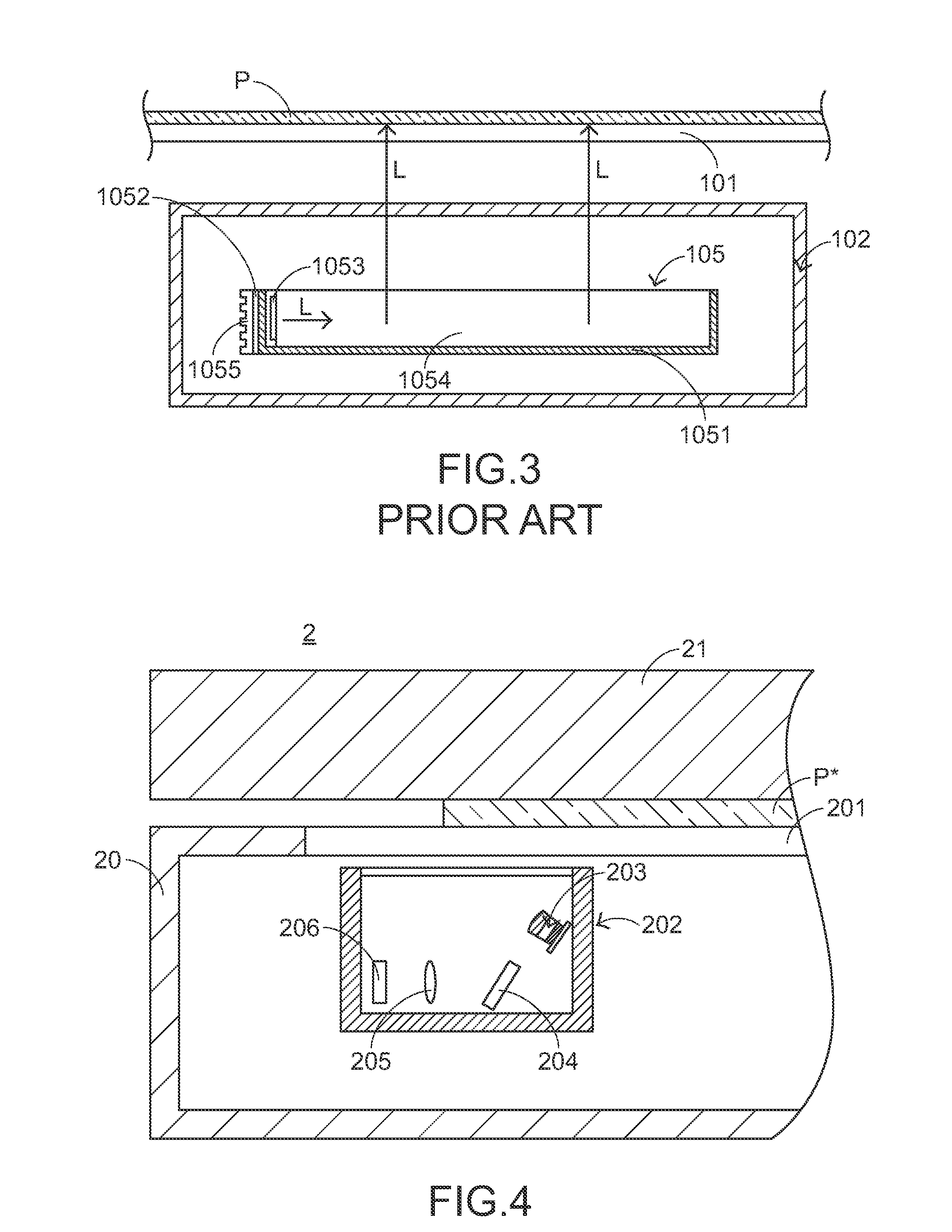
[0035]For obviating the drawbacks encountered from the prior art, the present invention provides a light guide module of a scanning apparatus. FIG. 4 is a schematic side view illustrating a light guide module of a scanning apparatus according to the present invention. As shown in FIG. 4, the scanning apparatus 2 comprises a lower casing 20 and an upper cover 21. The lower casing 20 comprises a glass platform 201 and a scanning module 202. The glass platform 201 is used for scanning a to-be-scanned document P*. During the scanning operation is performed, the scanning module 202 is moved within the lower casing 20 to scan the document P*. The scanning module 202 comprises a light guide module 203, a fixed reflective mirror 204, a lens 205 and an optical sensing element 206. The configurations and the functions of the light guide module 203, the fixed reflective mirror 204, the lens 205, the optical sensing element 206 and the moving mechanism of the scanning module 202 are similar to ...

third embodiment

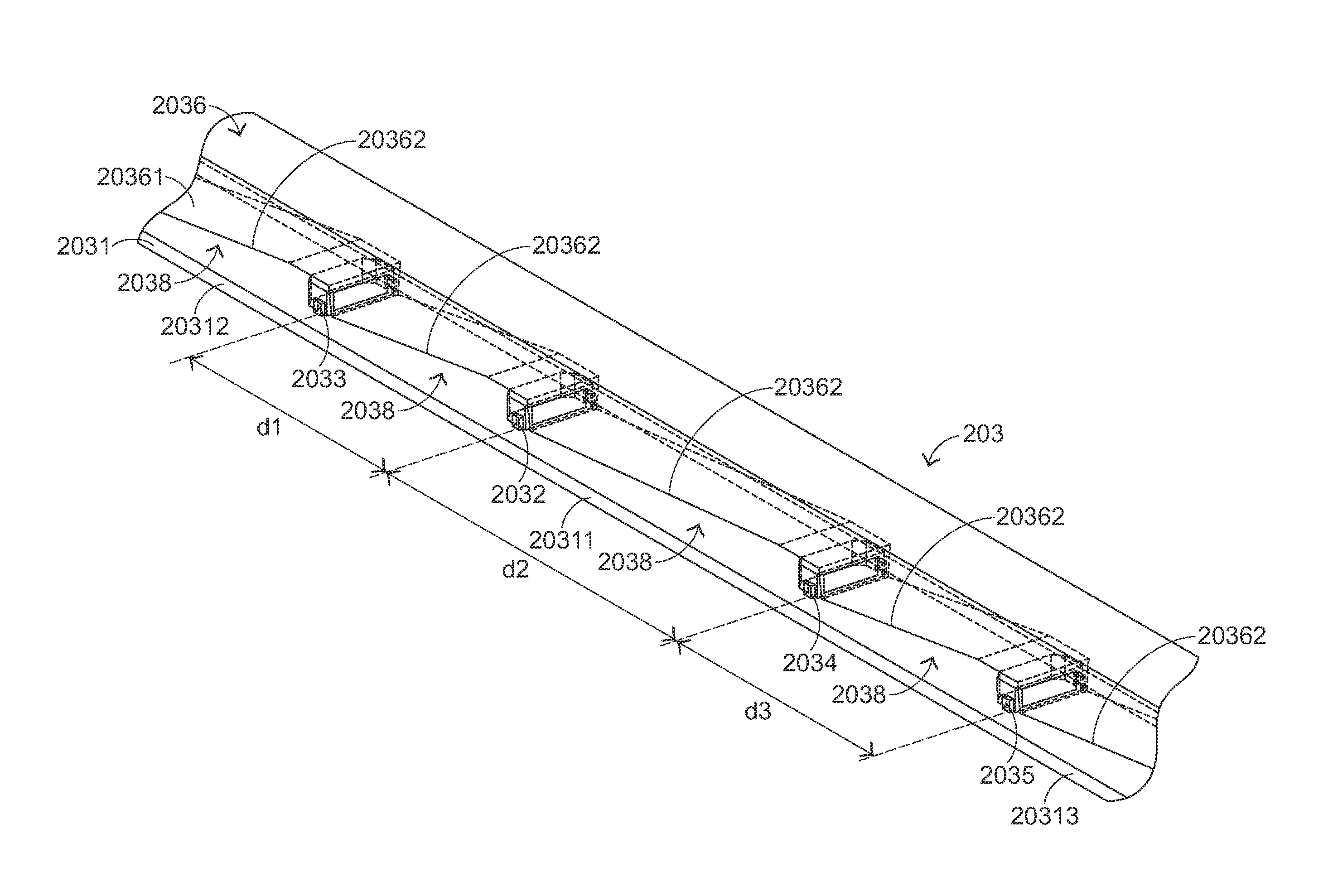
[0045]FIG. 8 is a schematic side view illustrating a light guide module of a scanning apparatus according to the present invention. The light guide module 403 comprises a circuit board 4031, a first side-emitting LED 4032, a second side-emitting LED 4033, a third side-emitting LED 4034, a fourth side-emitting LED 4035, a light-guiding post 4036, plural front-emitting LEDs 4037, a fifth side-emitting LED 4039, a sixth side-emitting LED 4040 and a seventh side-emitting LED4041.

[0046]Except for the following features, the configurations and the functions of the light guide module 403 are similar to those of the light guide module of the second embodiment, and are not redundantly described herein. For example, each of the reflective structures 40362 on the bottom 40361 of the light-guiding post 4036 includes plural salient points for reflecting the light beams L1˜L7, wherein the seventh light beam L7 is emitted by the seventh side-emitting LED 4041. In comparison with the reflective str...

fourth embodiment

[0048]FIG. 9 is a schematic side view illustrating a light guide module of a scanning apparatus according to the present invention. The light guide module 503 comprises a circuit board 5031, a first side-emitting LED 5032, a second side-emitting LED 5033, a third side-emitting LED 5034, a fourth side-emitting LED 5035, a light-guiding post 5036, plural front-emitting LEDs 5037, a fifth side-emitting LED 5039, a sixth side-emitting LED 5040, a seventh side-emitting LED 5041 and an eighth side-emitting LED 5042.


PUM


Abstract

A light guide module of a scanning apparatus includes plural side-emitting light emitting diodes and a light-guiding post, which are disposed on a circuit board. The light-guiding post has plural reflective structures corresponding to respective side-emitting light emitting diodes for receiving light beams from respective side-emitting light emitting diodes. A spacing interval between two of the side-emitting light emitting diodes at a middle portion of the circuit board is greater than a spacing interval between two of the side-emitting light emitting diodes at a side of the circuit board.

Description

FIELD OF THE INVENTION[0001]The present invention relates to a light guide module, and more particularly to a light guide module of a scanning apparatus for guiding light beams.BACKGROUND OF THE INVENTION[0002]Scanning apparatuses are widely used for scanning images of paper documents. The scanned images can be converted into electronic files, which are then stored, processed or spread. With the maturity of scanning technologies, the scanning apparatuses have experienced great growth and are now rapidly gaining in popularity.[0003]FIG. 1 is a schematic perspective view illustrating a conventional scanning apparatus. As shown in FIG. 1, the conventional scanning apparatus 1 comprises a lower casing 10 and an upper cover 11. The lower casing 10 comprises a glass platform 101 and a scanning module 102. The glass platform 101 is used for scanning a to-be-scanned document P (see FIG. 2). After the document P is placed on the glass platform 101, the lower casing 10 is covered by the upper...

Claims


Application Information

Patent Timeline
IPC IPC(8): F21V8/00
CPCG02B6/002G02B6/0035G02B6/0046G02B6/0068H04N1/02885G02B6/008H04N1/02825H04N1/02835H04N1/02865G02B6/0073
Inventor CHANG, YU-CHENG
Owner PRIMAX ELECTRONICS LTD
Why Eureka
Try Eureka