Colorless, directionless, and gridless optical network, node, and method

a colorless, directionless, gridless, optical network technology, applied in the field of optical networking, can solve the problems of difficult network modification, high cost, and the likelihood of increasing the density of wavelengths on which different data signals may be transported

Active Publication Date: 2012-07-19
CIENA
View PDF3 Cites 53 Cited by
  • Summary
  • Abstract
  • Description
  • Claims
  • Application Information

AI Technical Summary

Benefits of technology

[0012]In yet another exemplary embodiment, a method includes broadcasting a plurality of optical signals over a plurality of ports using a broadcast element; selectively receiving a desired signal from all of the plurality of optical signals at one of the plurality of ports; and blocking the plurality of signals via a blocking element in line with one of the plurality of ports thereby preventing a multiple path of the broadcast plurality of optical signals. The method can further include selectively receiving the desired signal through tuning a tunable coherent receiver.

Problems solved by technology

However, they are relatively expensive because, among other reasons, they are relatively complex and incorporate active optical elements.
Furthermore, it is difficult to alter a network after it has been set up using such components.
As technology improves, the wavelengths on which different data signals may be transported are likely to become increasingly densely packed.
Therefore, to change the wavelengths used in an existing network built using fixed OADMs would potentially require replacement of some or all of the fixed OADMs in the network, which is an expensive proposition to the point of being impractical in many cases.
These channel filters introduce loss and signal distortion, thus limiting the number of ROADMs that a signal may pass through before it is too attenuated and / or distorted to be adequately detected at a receiver.

Method used


Image

  • Colorless, directionless, and gridless optical network, node, and method
  • Colorless, directionless, and gridless optical network, node, and method
  • Colorless, directionless, and gridless optical network, node, and method

Examples


Embodiment Construction

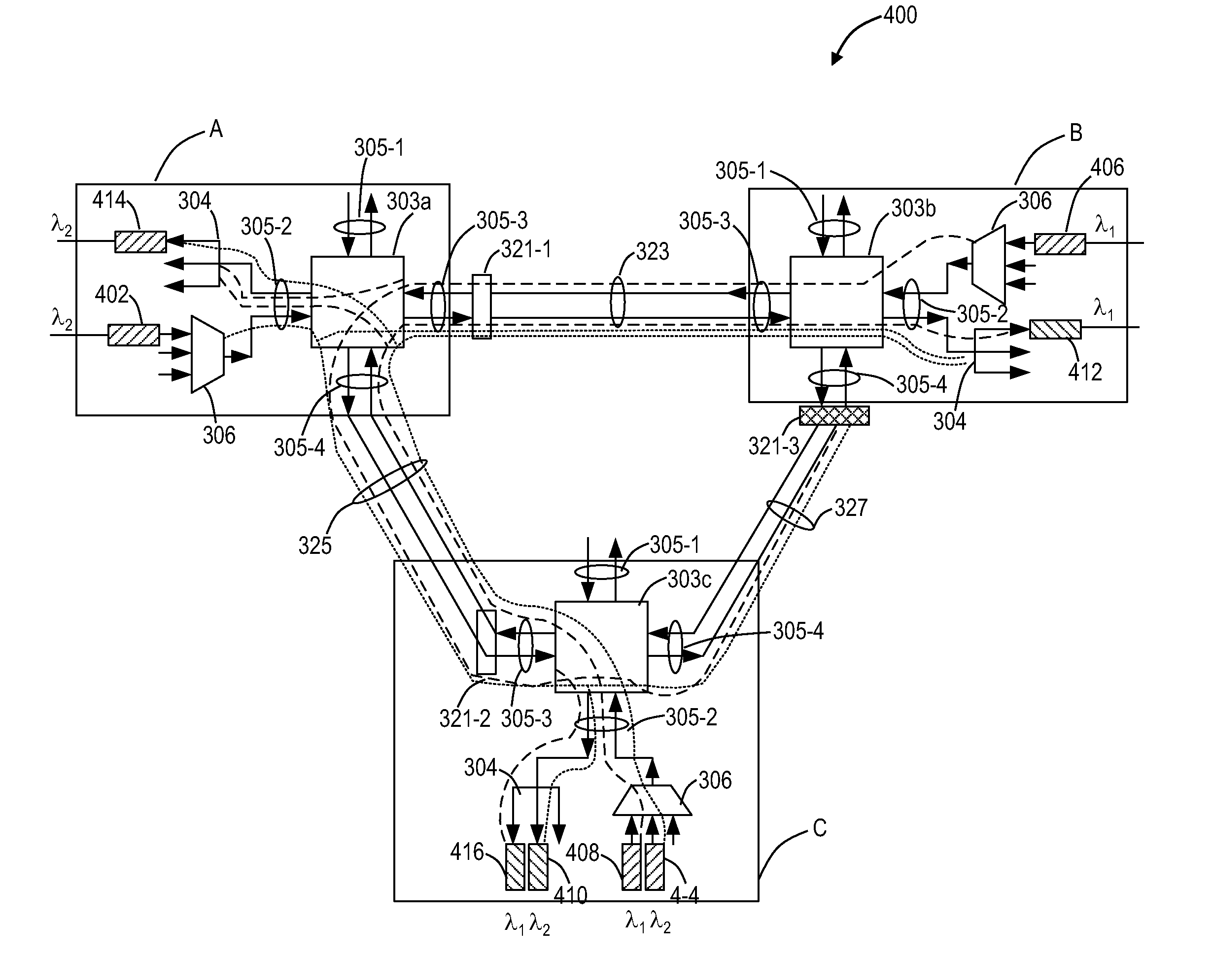
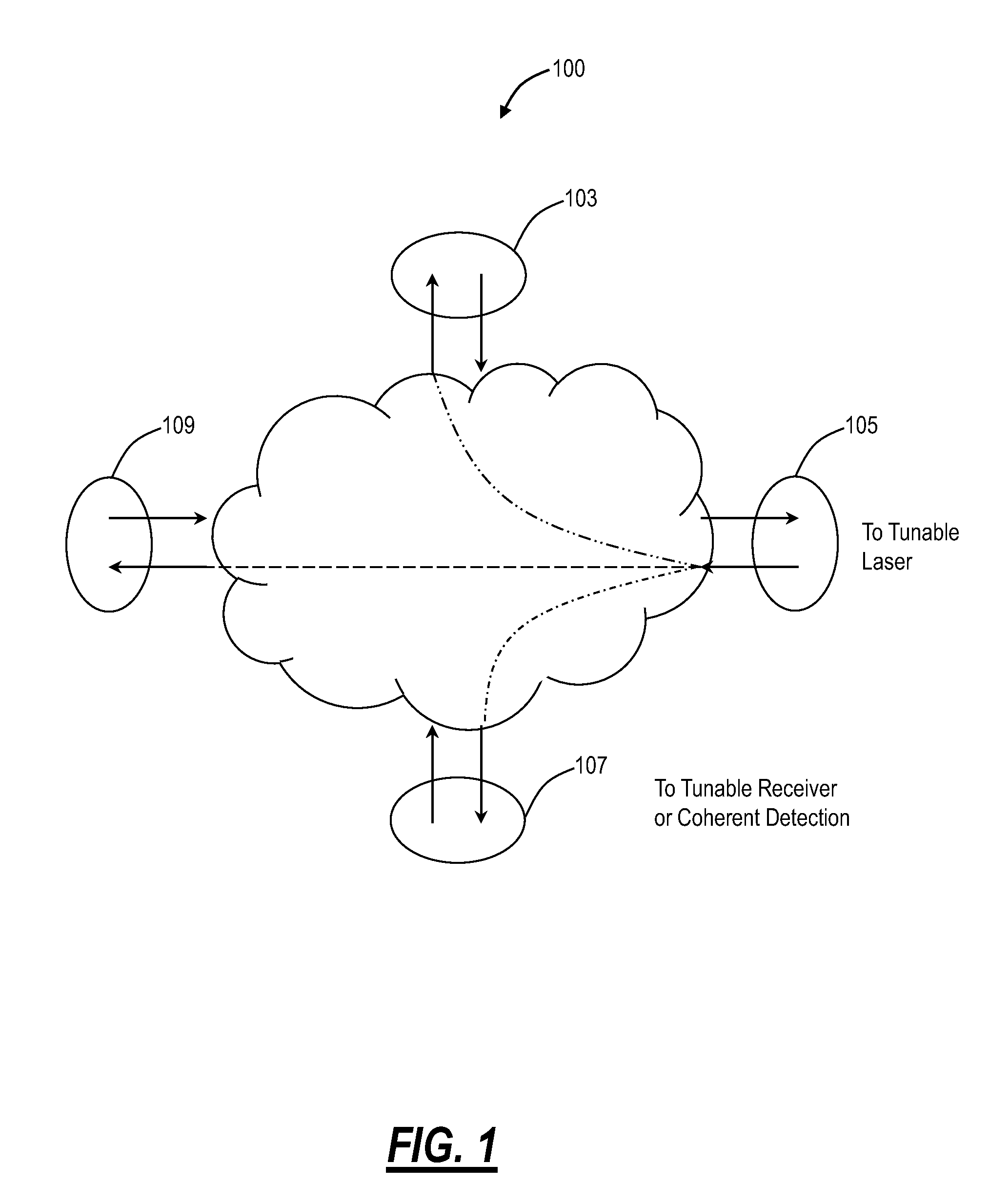
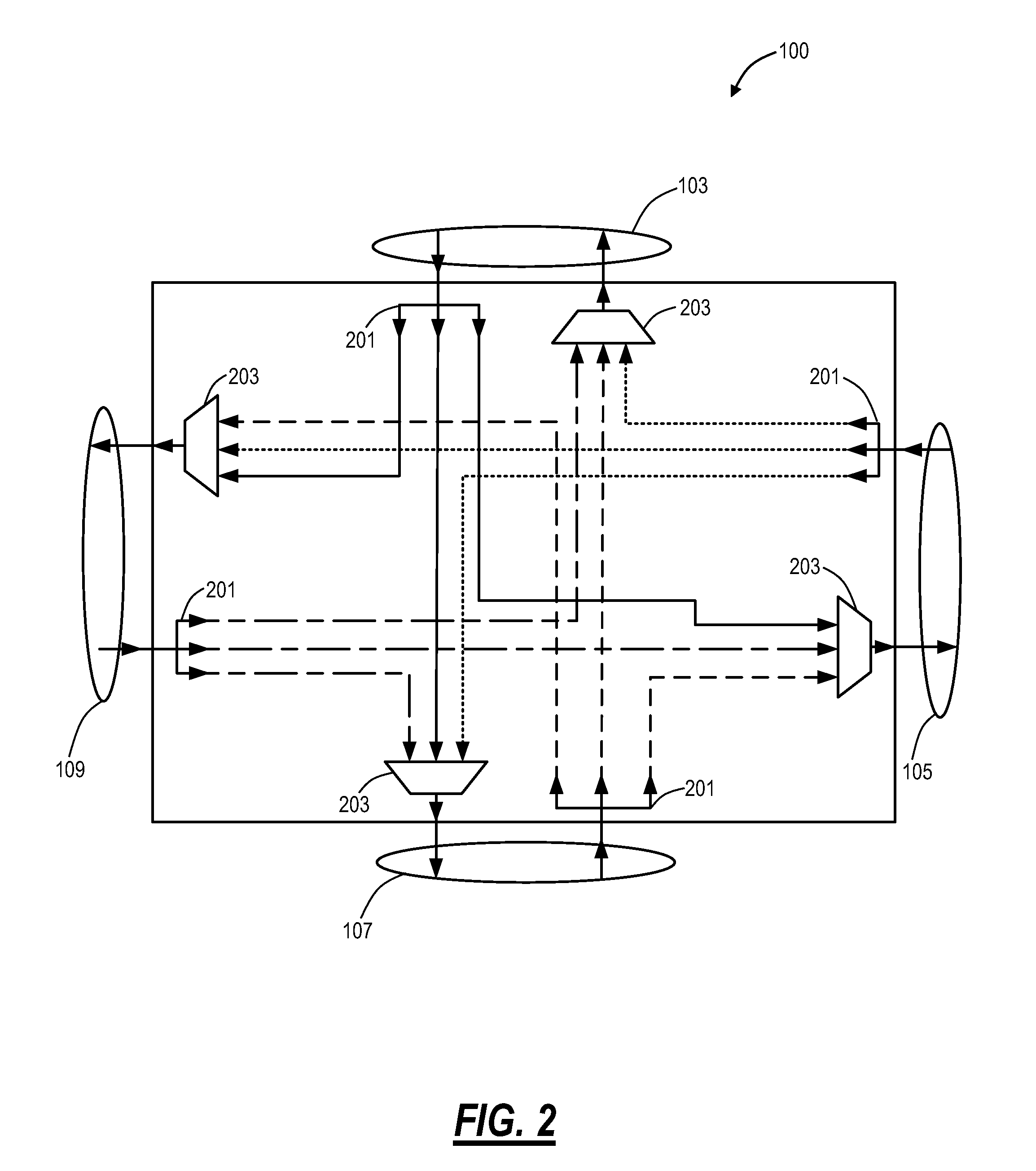
[0038]In various exemplary embodiments, the colorless, directionless, and gridless optical network, node, and method described herein relates to an all-broadcast optical layer where coherent optical receivers are used like a radio receiver to tune into a channel of interest with all channels available at all drop points. Advantageously, this approach does not rely on WSSs while simultaneously providing a colorless, directionless, and gridless approach. The main issue in this network approach is also its inherent advantage in that since light is broadcast everywhere, there is the potential for multiple optical paths (e.g., optical loops) which cause interference, and potentially lasing. As such, the network approach can utilize optical blocking elements enable the broadcast optical channels to nodes via a single path for each of the optical channels, i.e. the optical blocking elements prevent multiple paths by constraining each channel to a single path. As is described herein, manipu...


PUM


Abstract

An optical node includes an optical routing apparatus including N ports, N is an integer greater than 2, the optical routing apparatus configured to direct light that is input to each of the N ports to all of the other N ports, and a configurable optical blocking element located in line with at least one of the N ports. A method includes broadcasting a plurality of optical signals over a plurality of ports using a broadcast element, selectively receiving a desired signal from all of the plurality of optical signals at one of the plurality of ports, and blocking the plurality of signals via a blocking element in line with one of the plurality of ports thereby preventing a multiple path of the broadcast plurality of optical signals.

Description

CROSS-REFERENCE TO RELATED APPLICATION(S)[0001]This application is a continuation-in-part of co-pending U.S. patent application Ser. No. 12 / 436,470 filed May 6, 2009, and entitled “OPTICAL ROUTING DEVICE AND OPTICAL NETWORK USING SAME,” the contents of which are incorporated in full by reference herein.FIELD OF THE INVENTION[0002]Generally, the field of art of the present disclosure pertains to optical networking, and more particularly to a colorless, directionless, and gridless optical network, node, and method.BACKGROUND OF THE INVENTION[0003]Optical networks are becoming increasingly common because of the extremely wide bandwidth that can be supported by optical transmission techniques. Many, if not most, optical networks utilize wavelength division multiplexing (WDM) or dense wavelength division multiplexing (DWDM) in order to maximize the amount of information that can be transported over the network per unit time (i.e., data bandwidth). Like all information networks, switching...

Claims


Application Information

Patent Timeline
Patent Type & Authority Applications(United States)
IPC IPC(8): H04J14/02
CPCH04J14/0204H04J14/0294H04J14/0213H04J14/022H04J14/0227H04J14/0286H04J14/0297H04Q11/0005H04Q2011/0015H04Q2011/0016H04Q2011/0018H04J14/0268H04J14/0275H04J14/0238H04J14/0291H04J14/0206
Inventor BOERTJES, DAVID WELDONZOTTMAN, HARALD
Owner CIENA
Why Eureka
Try Eureka