
Breakaway outdoor signs

a technology for outdoor signs and signs, applied in the field of outdoor advertising signs, can solve the problems severe damage to advertising displays, damage that requires costly replacement and repair, and wind damage to signs, so as to eliminate or greatly reduce the likelihood of damage to signs, and use of displays can.

Active Publication Date: 2012-07-26
NABORS JR ROBERT L
View PDF8 Cites 10 Cited by
  • Summary
  • Abstract
  • Description
  • Claims
  • Application Information

AI Technical Summary

Benefits of technology

[0011]More particularly, the present invention relates to a sign of this type which includes a display support mounted on the top of the support column to permit pivotal movement of the advertising display when the display is subjected to wind forces exceeding a predetermined value. When the display includes an illumination source with wiring extending through the support column to the display, the present invention allows rotation of the display without damage to or disconnection of the wiring.
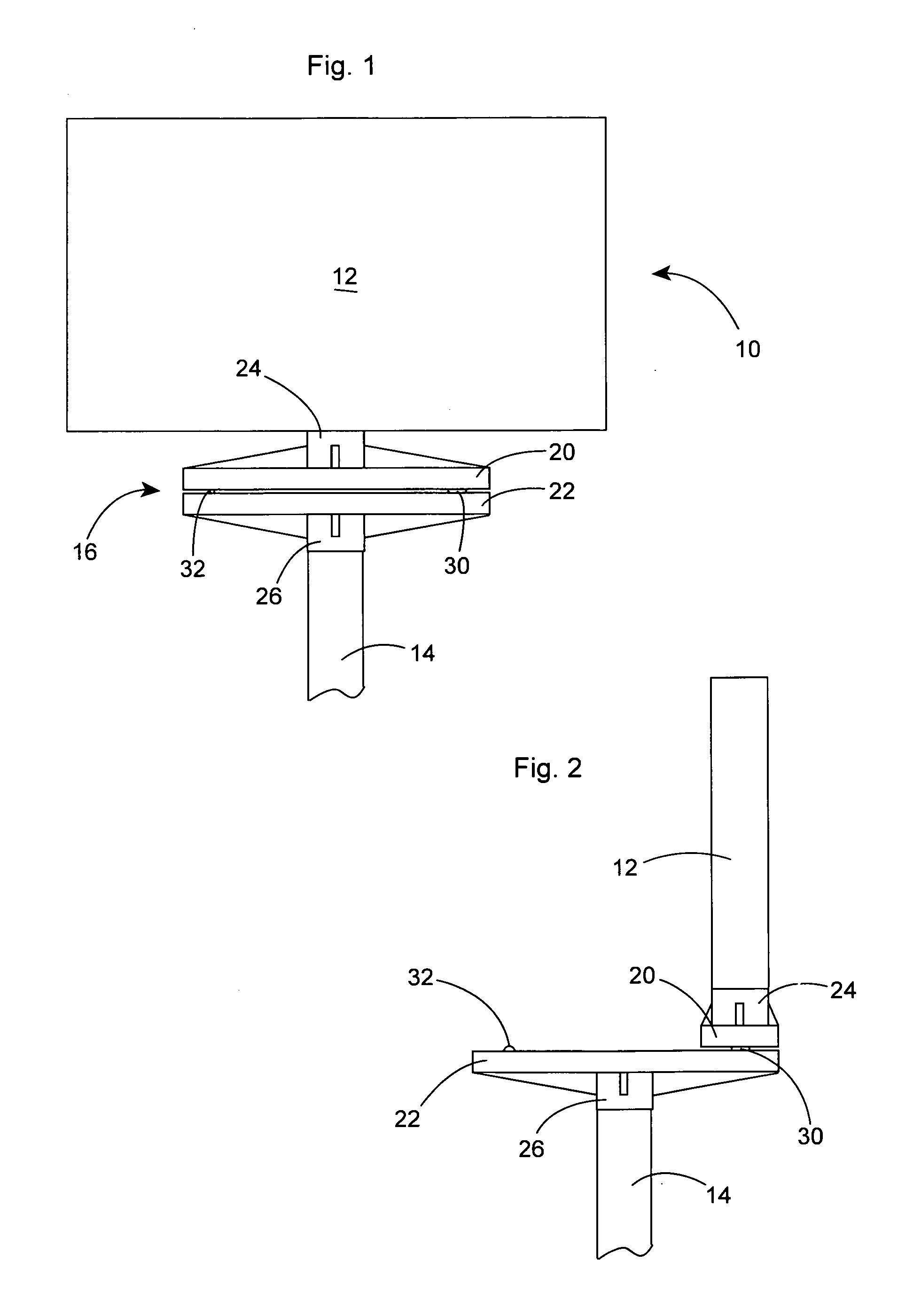
[0012]More specifically, the present sign, also referred to herein as a billboard, is comprised of an advertising display that is mounted using an unique support mechanism onto a vertical support column so that the display can pivot when subjected to a wind of greater than a predetermined force without damage to the display or any electrical connection.
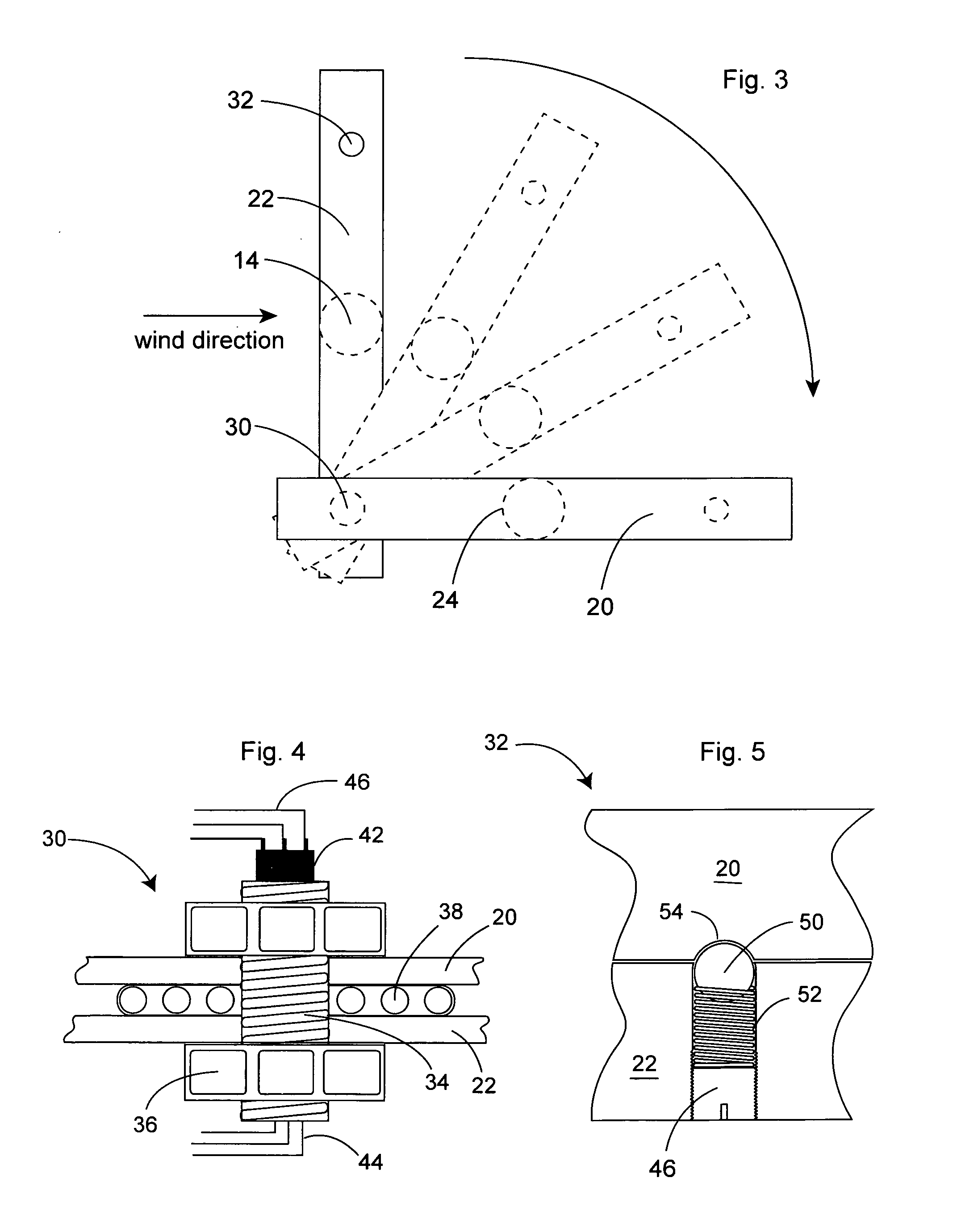
[0016]The support arms are joined adjacent one end by a vertical pivot mechanism which is laterally offset to one side of the central axis of the advertising display and the column. The pivot mechanism is comprised of a threaded cylindrical pivot shaft. The upper end of the pivot shaft is joined to the upper support arm, while the lower end of the pivot shaft is joined to the lower support arm. The shaft is designed to be rotatable relative to at least one of the support arms so that the upper support arm and display can rotate about the pivot shaft relative to the lower support arm and the support column.
[0017]The pivot shaft is secured to the upper and lower arms by nuts threaded onto the ends of the shaft. A ball bearing ring surrounds the pivot shaft and abuts the facing surfaces of the upper and lower arms to impart ease of rotation and also to prevent up and down motion of the distal end of the upper arm.
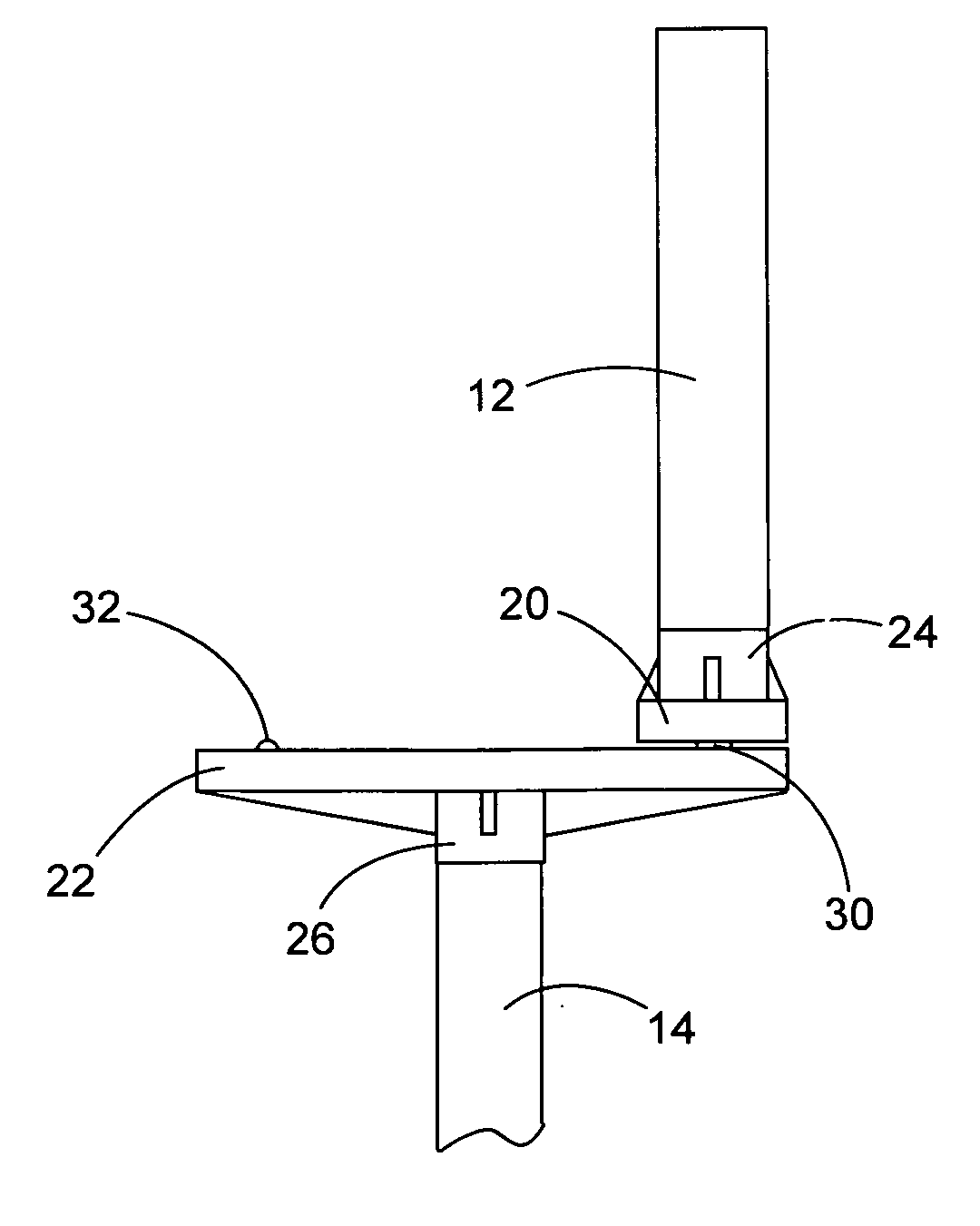
[0022]When a wind force is experienced either on the front face or the rear face of the advertising display at speed that is in excess of the preset value, the torque against the advertising display forces the retainer against the force of the spring unseating the retainer from the recess, and allowing the advertising display to rotate freely about the vertical pivot shaft so that the advertising display swings away from the wind direction, orienting the face of the advertising display parallel to the wind direction with the side edge of the display closest to the pivot point being toward the wind. In this orientation the force against the display is minimized, thereby eliminating or greatly reducing the likelihood of damage to the sign.
[0023]After conditions return to normal, the advertising display is simply rotated back to its original position so that the retainer is again urged into the recess, thereby securing the display in its original operative position. Since the electrical connection to the display illumination source is not broken, use of the display can be resumed without repairs being necessitated.

Problems solved by technology

Signs are subject to wind damage, particularly in hurricane prone areas, due to the large surface area presented by the advertising display when the display is transverse to the wind direction, either at the front or back of the display.
High winds can cause severe damage to advertising displays, and even to the support structures, as well as to persons or property in the vicinity of the sign if a part of the sign is separated from the structure.
Such damage requires costly replacement and repair.
Construction of signs to withstand greater wind forces also results in additional cost.
While sign constructions described in the prior art may have been of some value in diminishing damage to signs as historically constructed, they are of little value in preventing damage to modern signs.

Method used


Image

  • Breakaway outdoor signs
  • Breakaway outdoor signs
  • Breakaway outdoor signs

Examples


Embodiment Construction

[0031]In the following description, terms such as horizontal, upright, vertical, above, below, beneath, and the like, are used solely for the purpose of clarity in illustrating the invention, and should not be taken as words of limitation. The drawings are for the purpose of illustrating the invention and are not intended to be to scale.

[0032]As illustrated in the drawings, a preferred embodiment of the breakaway sign, generally 10, is comprised of an advertising display 12, a vertical support pole or column 14, and a support mechanism 16. Support mechanism 16 is comprised of an upper support arm 20, a lower support arm 22. An upper sleeve 24 adapted for attachment to the bottom of display 12 projects upward from the top of upper support arm 20, while a lower sleeve 26 adapted for attachment to the top of column 14 projects downwardly from the bottom of lower support arm 22. Column 14, display 12 and sleeves 24 and 26 have a common vertical axis.

[0033]Pivot mechanism 30, illustrated...


PUM


Abstract

An outdoor sign resistant to wind damage includes a support column; a display having secured and released positions, a lower edge and a central vertical axis aligned with the axis of the column when the sign is in the secured position; a lower horizontal arm with opposed ends mounted on the upper end of the support column; an upper horizontal arm with opposed ends attached to the display, the upper arm being parallel to the display lower edge and the lower support arm when the display is in the secured position; a pivot mechanism joining the support arms adjacent one end; and a retainer mechanism between the opposite ends of the support arms, the mechanism releasibly securing the support arms to each other when the sign is in the secured position. The retainer mechanism is unlatched when the wind force is greater than a predetermined value.

Description

[0001]This application claims the benefit of the filing date of U.S. Provisional Application No. 61 / 461,840, filed Jan. 24, 2011, which is incorporated herein by reference in its entirety.BACKGROUND OF THE INVENTION[0002](1) Field of the Invention[0003]The present invention relates to outdoor advertising signs, and in particular to signs including means for permitting rotation of the sign advertising display about a vertical axis when the wind force exceeds a predetermined value.[0004](2) Description of the Prior Art[0005]Large outdoor advertising signs, also known as billboards, are comprised of an upper rectangular advertising display assembly, or simply display, supported on and elevated for viewing on a support pole or column. The advertising display may be constructed in different ways, but generally includes a frame having parallel upper and lower edges, and parallel side edges. The frame surrounds a rectangular panel for placement of advertisements. In most signs, the frame w...

Claims


Application Information

Patent Timeline
IPC IPC(8): G09F13/04G09F13/00G09F15/00
CPCG09F7/002G09F9/35G09F9/3026G09F15/0087G09F15/0037
Inventor NABORS, JR., ROBERT L.
Owner NABORS JR ROBERT L
Learn More