Contamination indicator

a technology of indicator and contaminant, applied in the direction of measuring device, separation process, instruments, etc., can solve the problems of increased pressure, insufficient contamination degree, risk,

Active Publication Date: 2019-06-04
HYDAC FILTERTECHNIK GMBH
View PDF13 Cites 0 Cited by
  • Summary
  • Abstract
  • Description
  • Claims
  • Application Information

AI Technical Summary

Benefits of technology

[0004]An object of the invention is to provide an improved contamination indicator of the above mentioned type, in which the display errors due to temperature-induced changes in the viscosity of the fluid are minimized.

Problems solved by technology

The known manner in which such contamination indicators function is based on the fact that an increase in pressure in the fluid intake (i.e., the dirty side in the filtering process) is associated with increasing contamination of the filter element.
If a hydraulic system is put into operation in a cold state, risk exists that the indicating device of the contamination indicator will signal a degree of contamination that falls below a threshold value that has been predefined as acceptable.
In the case of a cold start-up and during the cold phases before reaching the normal operating temperature, which may be in the range of 40° C. for example, the pressure that arises on the dirty side will then signal an insufficient degree of contamination.

Method used


Image

  • Contamination indicator
  • Contamination indicator
  • Contamination indicator

Examples


Embodiment Construction

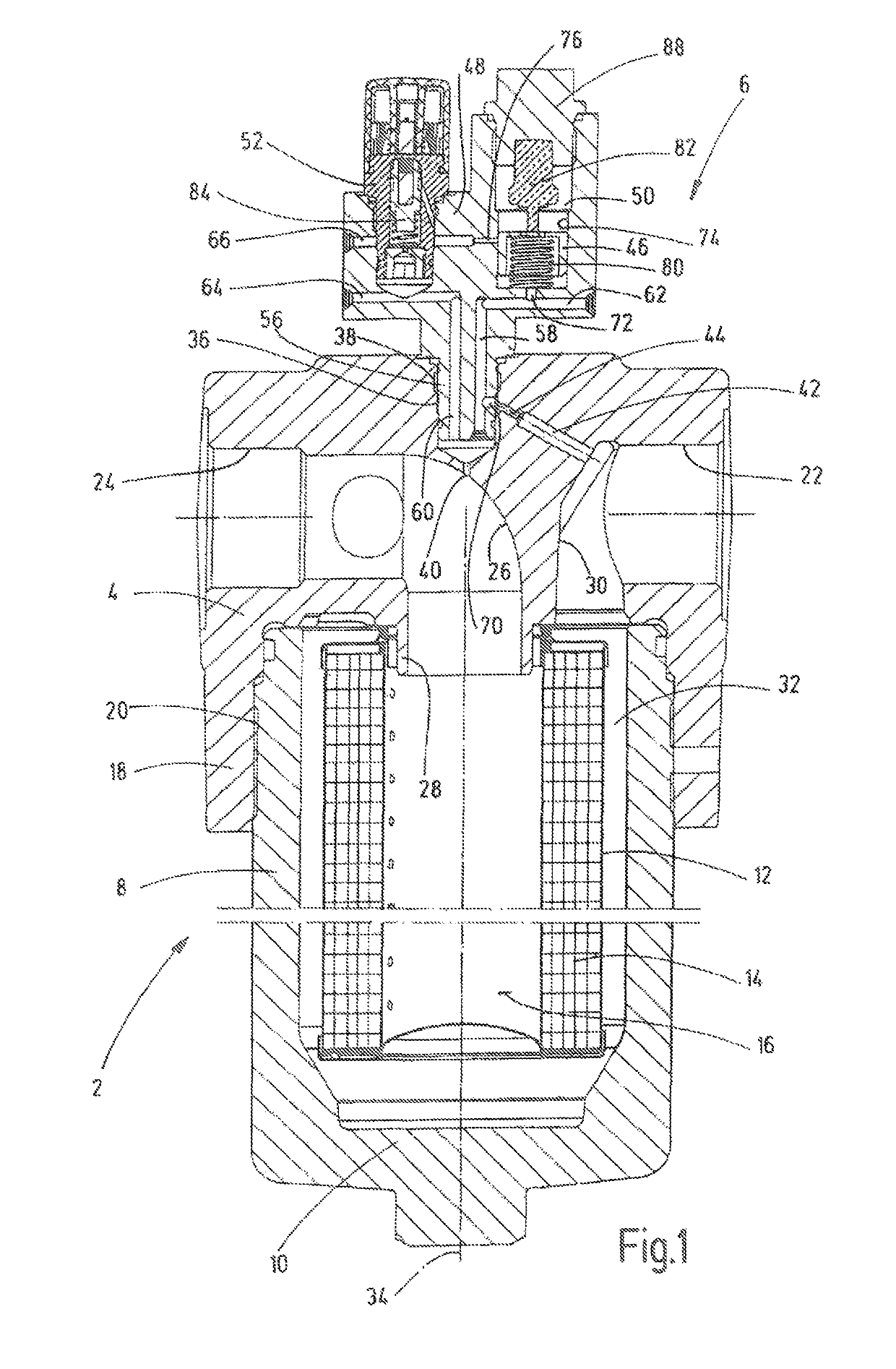
[0030]In FIG. 1 a filter housing 2 has an adapter with a contamination indicator 6 has been attached to the removable filter head 4 of the housing. The filter housing 2 has a circular cylindrical filter bowl 8 with a closed bottom 10. A replaceable filter element 12 can be housed in the bowl 8. The filter element is formed in a known manner and has a filter material 14 that forms a hollow cylinder. Fluid can pass through the filter material from the outside into an inner filter cavity 16 during operation. The filter head 4, which seals the upper, open end of the filter bowl 8, has a connection part 18 that overlaps the upper opening edge of the bowl 8, with which the head 4 can be connected with the bowl 8 by a thread 20. The filter head 4 can be removed for inserting and exchanging a filter element 12.

[0031]The filter head 4 has ports, which form a fluid inlet 22 and a fluid outlet 24. A fluid passage 26 is connected to the fluid outlet 24 and opens into the inner filter cavity 16 ...


PUM

PropertyMeasurementUnit
temperatureaaaaaaaaaa
pressureaaaaaaaaaa
temperatureaaaaaaaaaa

Abstract

A contamination indicator is for filter elements (12) for fluids that are replaceably housed in a filter housing (2). The indicator has a fluid-conveying connection (58) to the interior of the housing (2) and possesses an indicating device (52) providing information concerning the degree to which the filter element is contaminated (12). A temperature-dependently active actuation device (50) is connected upstream from the indicating device (52) in the direction of fluid inlet. By the actuation device, the indicating device (52) is activated when the fluid temperature has reached a predefinable threshold value.

Description

FIELD OF THE INVENTION[0001]The invention relates to a contamination indicator for filter elements for fluids that are replaceably housed in a filter housing. The indicator has a fluid-conveying connection to the interior of the housing and possesses an indicating device. The indicator device provides information concerning the degree to which the filter element is contaminated.BACKGROUND OF THE INVENTION[0002]Contamination indicators of this type are known in the prior art (DE 101 27 021 C1) and are used in hydraulic systems, in which replacement of used filter elements located in the fluid circuit with new filter elements is necessary once a certain degree of contamination has entered to maintain the operational reliability of the system. The known manner in which such contamination indicators function is based on the fact that an increase in pressure in the fluid intake (i.e., the dirty side in the filtering process) is associated with increasing contamination of the filter eleme...

Claims


Application Information

Patent Timeline
Patent Type & Authority Patents(United States)
IPC IPC(8): G01L19/12B01D35/143
CPCB01D35/143
Inventor JUNG, ARTURWENDELS, JORG MICHAEL
Owner HYDAC FILTERTECHNIK GMBH
Why Eureka
Try Eureka