Display module

a display module and module technology, applied in the field of display modules, can solve the problems of failure to perform one-time screw application of fasteners, unpreventable tolerances of display panels and other assembly elements, and misalignment of assembly holes, so as to improve the structural strength of the display module, simplify the assembly process, and reduce the number of required elements

Active Publication Date: 2012-05-01
COMPAL ELECTRONICS INC
View PDF13 Cites 2 Cited by
  • Summary
  • Abstract
  • Description
  • Claims
  • Application Information

AI Technical Summary

Benefits of technology

[0011]Accordingly, the present invention is directed to a display module with position limiting structure, which improves convenience in assembly.
[0028]The display module of the present invention has a position limiting structure, by which the structural strength of the display module is improved. Also, there needs no screws or adhesives in the assembly of the bracket and the frame, and thus the number of required elements can be reduced, the assembly process can be simplified and the display module can be minimized to achieve the market requirements of cost reduction and thinness.

Problems solved by technology

However, in the manufacturing of the display panel, unpreventable tolerances are exist in the size of the display panel and other assembly elements.
As regards to the assembly elements, manufacturing tolerances are usually caused by plastic injection molding process, which may lead to misalignment of assembly holes due to difference in dimension thereof.
The aforementioned manufacturing tolerance results in failure of performing one-time screw when applying the fastener.
The repeated screwing action generates inconvenience in assembly, prolongs working hours and affects the productive yields.
Furthermore, the complicated assembly process may also lead to defectives and thereby increase the manufacturing cost.
Another conventional manner of assembly is performed by adhesive, which causes long working hours and the adhesive can not be repeatedly used.
When an error occurs in the assembly process, the adhesive should be removed destructively to perform reproduction, which may result in not only residual of adhesive but also damage of the display panel.

Method used


Image

  • Display module
  • Display module
  • Display module

Examples


Embodiment Construction

[0034]Reference will now be made in detail to the present preferred embodiments of the invention, examples of which are illustrated in the accompanying drawings. Wherever possible, the same reference numbers are used in the drawings and the description to refer to the same or like parts.

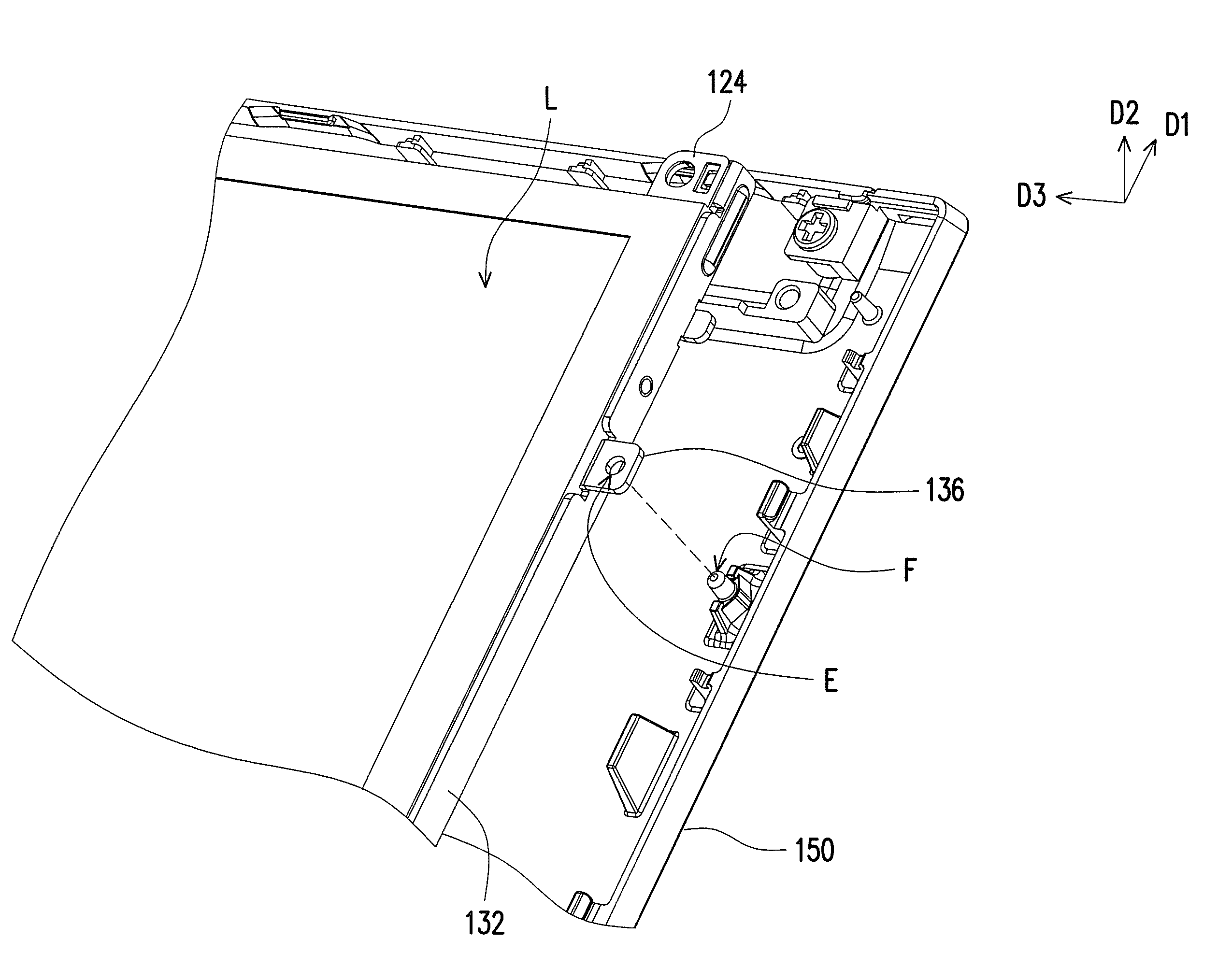
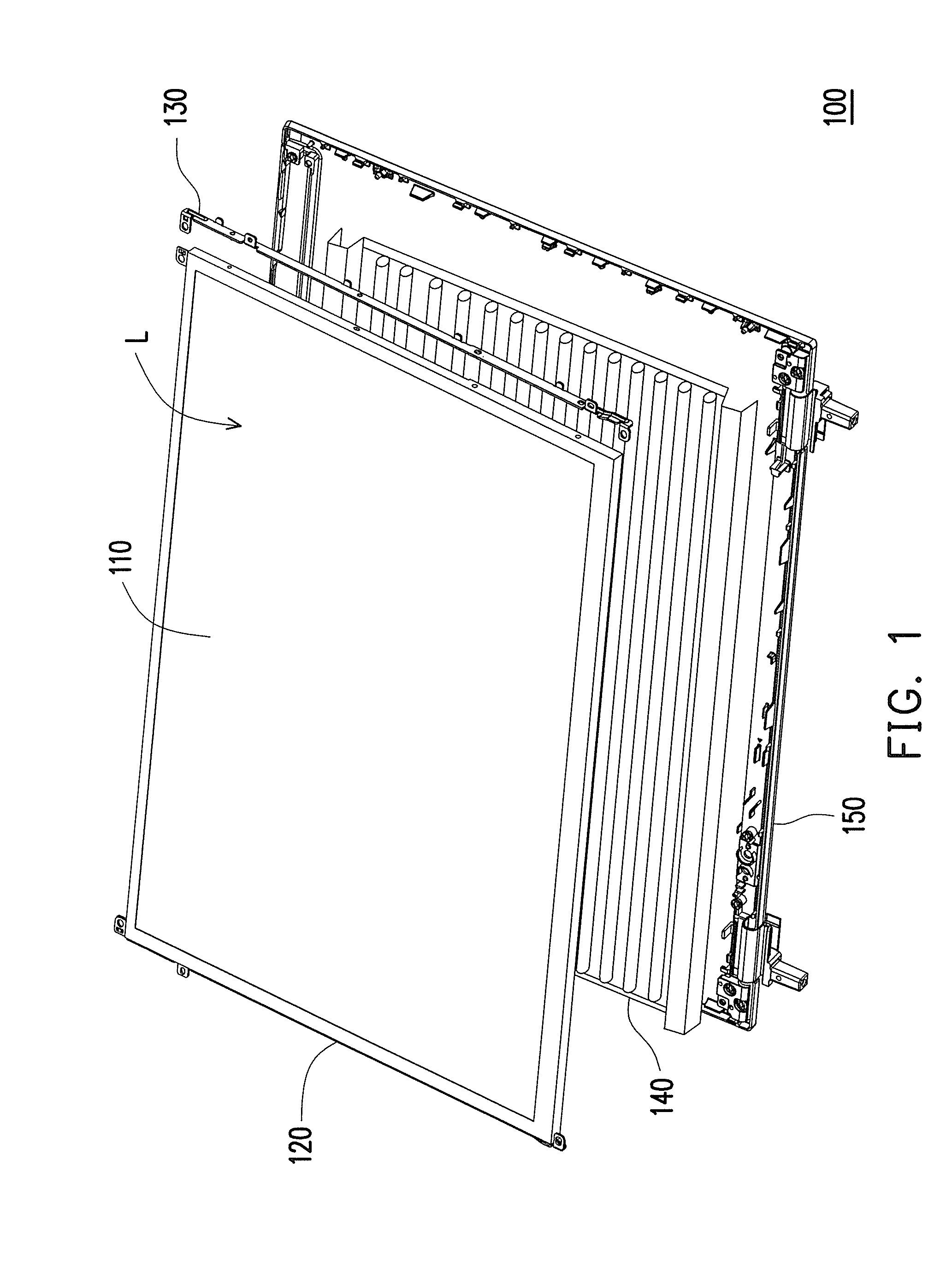
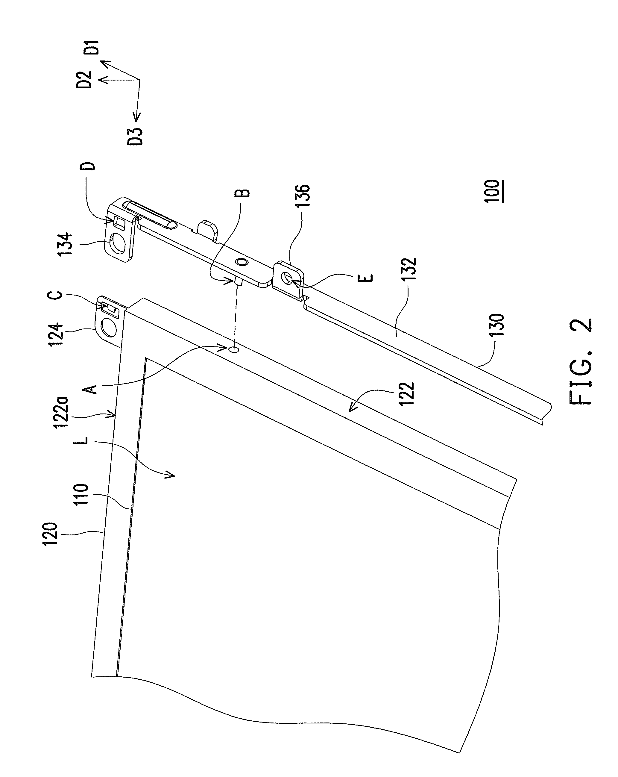
[0035]FIG. 1 is a perspective view of a display module according to an embodiment of the present invention. FIG. 2 is a partial view of the display module as illustrated in FIG. 1. Referring to FIG. 1 and FIG. 2, the display module 100 comprises a display panel 110, a frame 120 and a bracket 130. The display panel 110 has a display surface L.

[0036]The frame 120 surrounds the display panel 110. The frame 120 has a protruding part 124 and a first position limiting structure A, wherein the first position limiting structure A can be a hole or a cavity. In addition, the material of the frame 120 of the present embodiment includes metal, in which the aluminum with superior ductility, good strength and ligh...


PUM

PropertyMeasurementUnit
lengthaaaaaaaaaa
sizeaaaaaaaaaa
dimensionaaaaaaaaaa

Abstract

A display module including a display panel, a frame and a bracket is provided. The frame surrounds the display panel and has a protruding part and a first position limiting structure. The bracket has a body with a second position limiting structure and a first protrusion, wherein the protruding part is aligned with the first protrusion when the first position limiting structure is engaged with the second position limiting structure to fix the bracket on the frame in a non-screw manner.

Description

CROSS-REFERENCE TO RELATED APPLICATION[0001]This application claims the priority benefit of Taiwan application serial No. 97147408, filed on Dec. 5, 2008. The entirety of the above-mentioned patent application is hereby incorporated by reference herein and made a part of this specification.BACKGROUND OF THE INVENTION[0002]1. Field of the Invention[0003]The present invention generally relates to a display module, and more particularly, to the display module provided with a position limiting structure.[0004]2. Description of Related Art[0005]With the development of electro-optical technique and semiconductor technique, various flat display panels (FDP), such as liquid crystal displays (LCDs), plasma display panels (PDPs) or organic electro-luminescent (OEL) devices have become necessaries on our daily life.[0006]To the design requirement of thinness, the display panel usually being fixed in a manner of side mounting. More specifically, after a frame is disposed on the display panel, t...

Claims


Application Information

Patent Timeline
Patent Type & Authority Patents(United States)
IPC IPC(8): G02F1/1333
CPCG02F1/133308G02F2201/465
Inventor CHANG, CHIN-HSIEN
Owner COMPAL ELECTRONICS INC
Why Eureka
Try Eureka