Blunt force protection headgear technology

a technology of headgear and blunt force, applied in the field of headgear, can solve the problems of providing little to no protection from momentum transfer, and achieve the effects of enhancing blunt force protection, increasing the weight or balance of the hat, and increasing the protection of blunt for

Inactive Publication Date: 2012-08-02
GUARDIAN PROTECTIVE TECH
View PDF4 Cites 21 Cited by
  • Summary
  • Abstract
  • Description
  • Claims
  • Application Information

AI Technical Summary

Benefits of technology

[0006]In certain embodiments impact absorbing material is incorporated into a cap or hat, or that creates a cap within a cap. Such caps provide increased blunt force protection in the event the wearer falls or. is struck with an object, such as a baseball or golf ball. For baseball cap embodiments, the pie shaped pieces that typically makeup a baseball cap have an inner liner sewn into the cap, creating pie piece shaped pockets between the two layers of fabric. The inner liner could be the same type of fabric as the outer layer, or could include a different material, such as a moisture wicking layer, that will come in contact with the scalp. The caps and hats typically are lightweight so as to not detract from the wearability factor of conventional hats or caps; the added materials typically do not increase the weight or balance of the hat in a detractable manner.
[0007]For helmet embodiments, pad kits are provided, which when inserted or attached to the inner surface of a helmet shell provide a user or wearer with enhance blunt force protection relative to padding in prior helmet systems. Pad kits according to various embodiments include pads having one or more layers of differing material, typically two or more layers of material; one layer including a rate sensitive, impact absorbing material, and another layer including a comfort or form-fitting material. The comfort layer is typically positioned to contact the user's head and provides enhanced comfort to the user, and the rate sensitive layer is typically positioned to contact the helmet shell and provides enhanced energy dissipation from a blunt force impact to the exterior of the helmet. Intervening, intermediate and adjacent layers of material, such as a fabric shell layer to wrap around and enclose a pad, are provided in certain embodiments.

Problems solved by technology

However, such materials typically provides little to no protection from transfer of momentum form a blunt force impact to the helmet shell.

Method used


Image

  • Blunt force protection headgear technology
  • Blunt force protection headgear technology
  • Blunt force protection headgear technology

Examples


Embodiment Construction

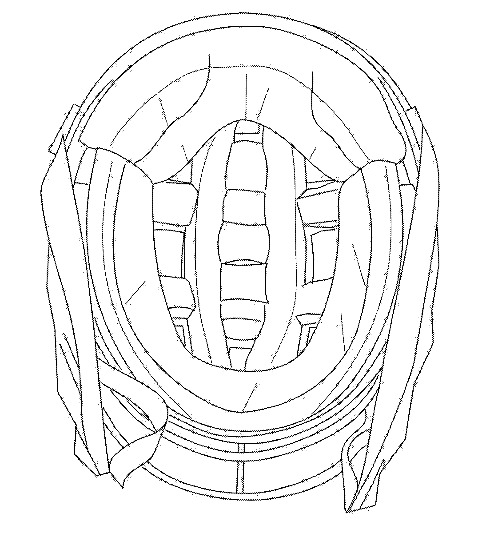
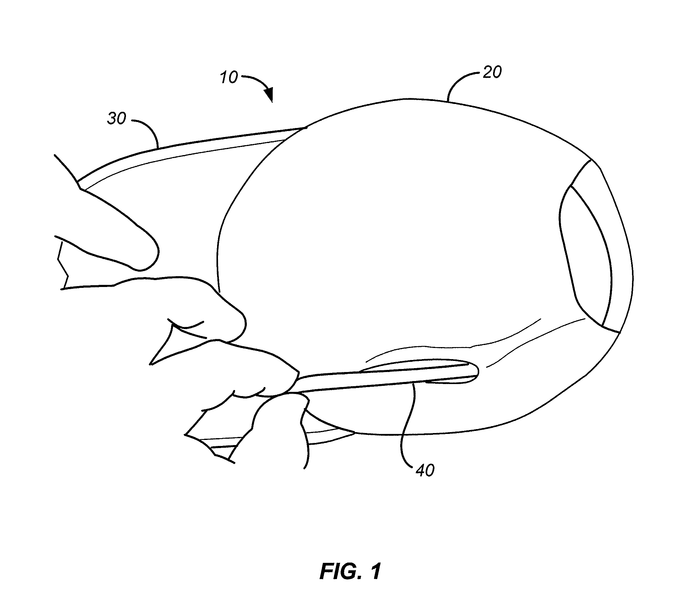
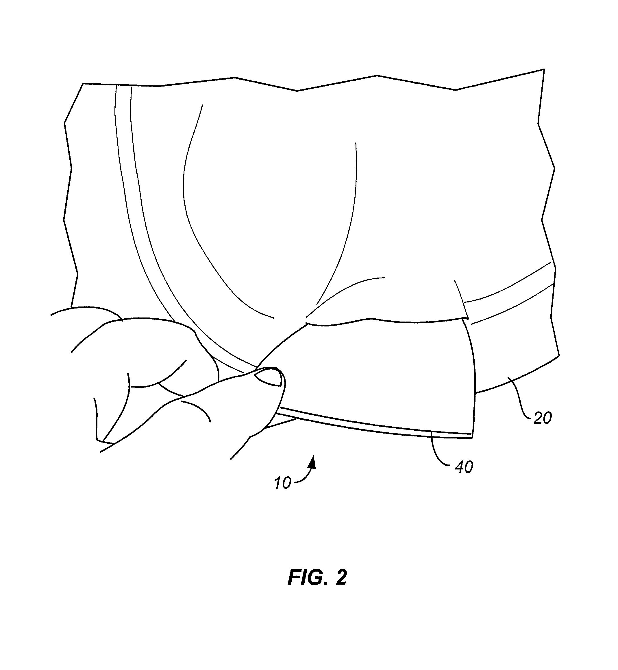
[0017]FIGS. 1-8 illustrate an embodiment of the present invention. It will be appreciated that FIGS. 1-8 illustrate a baseball cap embodiment, however, one skilled in the art will appreciate that embodiments are equally applicable to other types of headgear, such as beanies, caps, or other headgear for use in various applications including military applications, sporting events, etc. As shown in FIG. 1, headgear 10 according to one embodiment includes a cap portion 20 that is configured to cover a wearer's head. Cap portion 20 is typically made of a fabric material, such as a stitched cotton fabric. Cap portion may include various mechanisms as are well known to adjust the size of the perimeter to allow better coupling / attachment with different size heads, such as an elastic portion, Velcro, a belt and clasp mechanism, etc. Visor portion 30 is coupled with the cap portion. Visor portion 30 is optional in certain embodiments, e.g., beanies and other caps.

[0018]In one embodiment, a la...


PUM


Abstract

Helmets and pad kits for use in helmet shells are provided. The pad kits, when inserted or attached to the inner surface of a helmet shell, provide a user or wearer with enhance blunt force protection relative to padding in prior helmet systems. Pad kits include pads having one or more layers of differing material, typically two or more layers of material; one layer including a rate sensitive, impact absorbing material, and another layer including a comfort or form-fitting material. The impact absorbing material provides enhanced protection to the user's head from impact to the helmet shell.

Description

CROSS-REFERENCES TO RELATED APPLICATIONS[0001]The present application is a continuation-in-part of U.S. patent application Ser. No. 13 / 093,704, filed Apr. 25, 2011 (Attorney Docket No. 92668-804775 (000220US)), which claims the benefit of U.S. Provisional Application No. 61 / 327,573, filed Apr. 23, 2010 (Attorney Docket No. 92668-780107(000200US)), the disclosures of which are incorporated herein by reference in their entirety. The present application also claims the benefit of U.S. Provisional Application No. 61 / 415,624, filed Nov. 19, 2010 (Attorney Docket No. 92668-795284 (000210US)), the disclosure of which is incorporated by reference in its entirety.BACKGROUND[0002]The present invention relates generally to headgear, and more particularly to headgear, such as helmets, with improved impact resistant properties.[0003]Most caps and hats are made of a cloth or fabric or soft material that offers little in the way of protection from blunt force impact such as might occur when a base...

Claims


Application Information

Patent Timeline
Patent Type & Authority Applications(United States)
IPC IPC(8): A42B3/12
CPCA42B1/08F41H1/04A42B3/127
Inventor DIVINE, JOHNALFORD, SCOTTDENNIS, DAVID
Owner GUARDIAN PROTECTIVE TECH
Why Eureka
Try Eureka