Flexible seal for high voltage switch

Active Publication Date: 2012-08-02
THOMAS & BETTS INT INC
View PDF4 Cites 22 Cited by
  • Summary
  • Abstract
  • Description
  • Claims
  • Application Information

AI Technical Summary

Problems solved by technology

In conventional systems, the actuating mechanisms typically form a ground connection in the switch and, unless precautions are taken, current may arc from

Method used


Image

  • Flexible seal for high voltage switch
  • Flexible seal for high voltage switch
  • Flexible seal for high voltage switch

Examples


Embodiment Construction

[0009]The following detailed description refers to the accompanying drawings. The same reference numbers in different drawings may identify the same or similar elements.

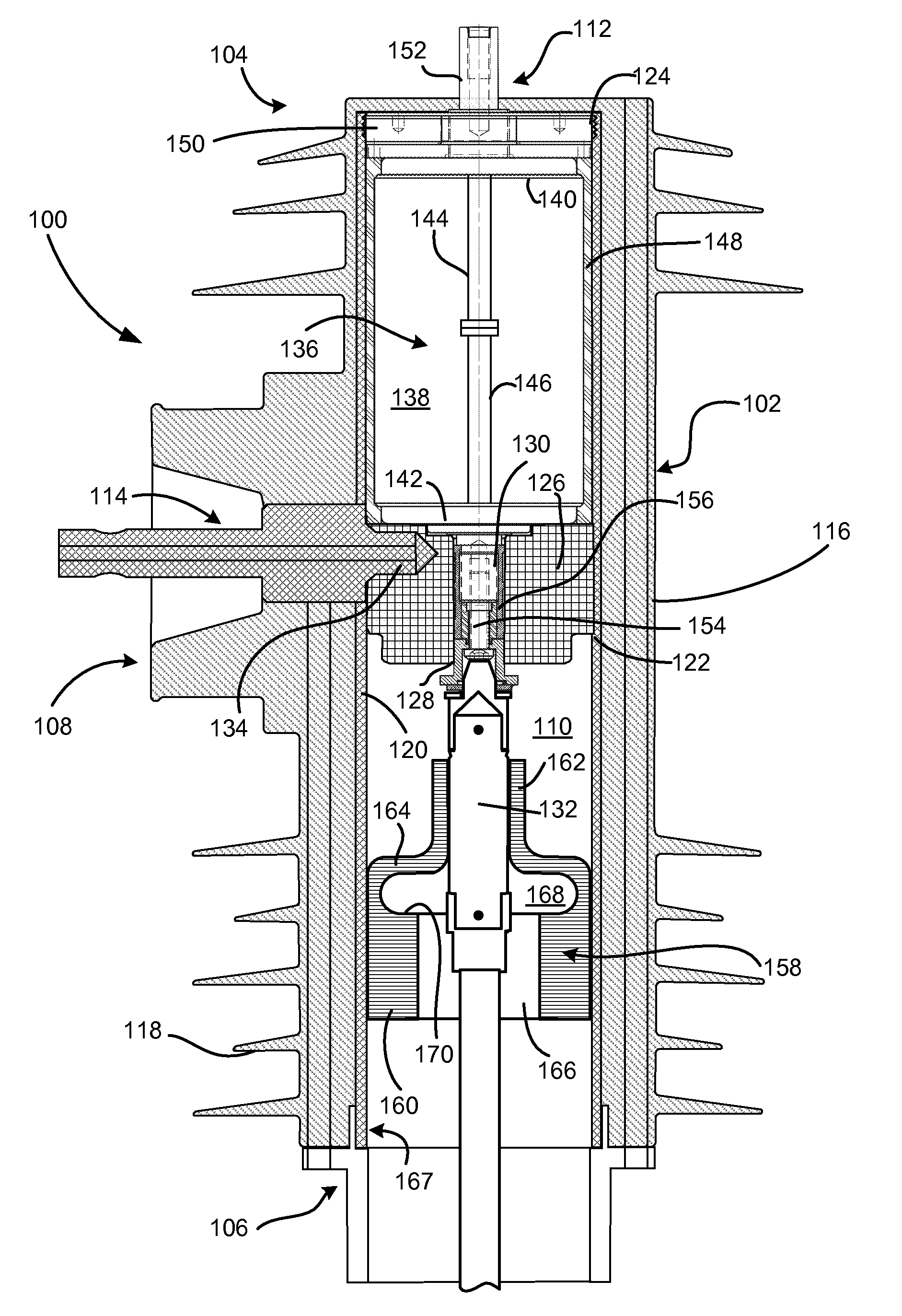
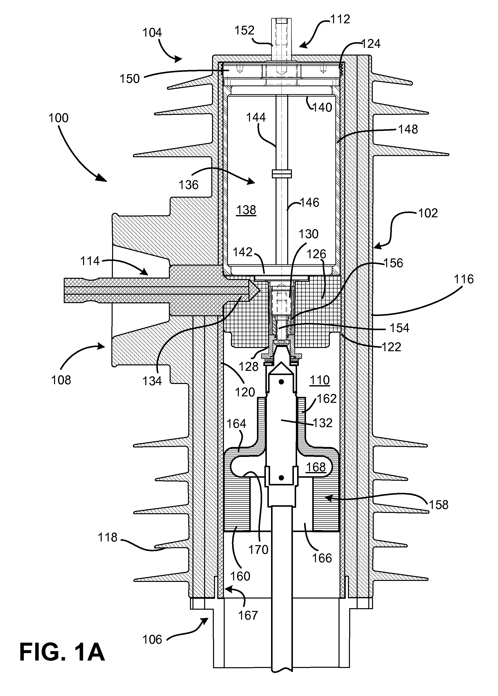
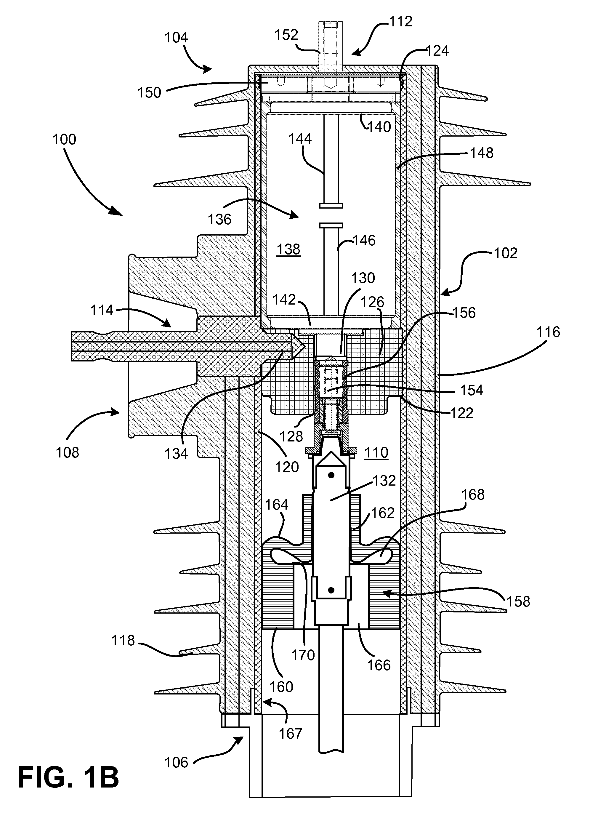
[0010]FIGS. 1A and 1B are schematic cross-sectional diagrams illustrating a high voltage switch 100 configured in a manner consistent with implementations described herein. As used in this disclosure with reference to the apparatus (e.g., switch 100), the term “high voltage” refers to equipment configured to operate at a nominal system voltage above 3 kilovolts (kV). Thus, the term “high voltage” refers to equipment suitable for use in electric utility service, such as in systems operating at nominal voltages of about 3 kV to about 38 kV, commonly referred to as “distribution” systems, as well as equipment for use in “transmission” systems, operating at nominal voltages above about 38 kV.

[0011]FIG. 1A illustrates switch 100 in an engaged (e.g., “on”) configuration and FIG. 1B illustrates switch 100 in a disengaged (e...


PUM


Abstract

An electrical switch includes a tubular housing that includes an interface positioned intermediate the conductor receiving end and the operating end. An operating rod extends through the housing. A fixed contact is electrically coupled to the operating end. A moveable contact is electrically coupled to the interface and the operating rod, wherein the moveable contact is moveable between a first position contacting the fixed contact and a second position separated from the fixed contact. A diaphragm is positioned in the tubular housing between the interface and the operating end and includes a first tubular portion and a second tubular portion. Movement of the operating rod from the first position to the second position causes the second tubular portion to move relative to the first tubular portion, thus deforming the shoulder portion.

Description

CROSS-REFERENCE TO RELATED APPLICATION[0001]This application claims priority under 35. U.S.C. §119, based on U.S. Provisional Patent Application No. 61 / 437,838 filed Jan. 31, 2011, the disclosure of which is hereby incorporated by reference herein.BACKGROUND OF THE INVENTION[0002]The present invention relates to the field of electrical switches and more particularly to an electrical switch whose contacts are located within an insulating environmental enclosure, such as a ceramic bottle. One of the contacts may be actuated by a mechanical system outside of the enclosure connected by a shaft extending through an enclosure seal.[0003]In conventional systems, the actuating mechanisms typically form a ground connection in the switch and, unless precautions are taken, current may arc from the switch assembly to the actuating mechanism, causing failure or damage. To address this, conventional high voltage switches, such as overhead reclosers typically utilize a lengthy fiberglass pull rod ...

Claims


Application Information

Patent Timeline
IPC IPC(8): H01H33/02
CPCH01H33/42H01H2033/426H01H33/666H01H33/08H01H33/53
Inventor BORGSTROM, ALAN D.
Owner THOMAS & BETTS INT INC
Why Eureka
Try Eureka