Wireless Field Device or Wireless Field Device Adapter with Removable Antenna Module

a wireless field device and antenna module technology, applied in the direction of antenna details, non-resonant long antennas, antennas, etc., can solve the problems of low energy utilization of the device, inability to cause sparks that may trigger explosions or fires, and limited power delivered by the wired network itsel

Active Publication Date: 2012-08-02
PHOENIX CONTACT DEVMENT & MFG
View PDF3 Cites 16 Cited by
  • Summary
  • Abstract
  • Description
  • Claims
  • Application Information

AI Technical Summary

Benefits of technology

The invention helps reduce built up electric charges within devices by allowing them to drain out into the surrounding environment without causing any electrical arcs. This happens through a special material that prevents damage during connection or disconnection.

Problems solved by technology

This patent describes a problem related to designing wireless field devices for use in hazardous environments. In these settings, traditional wirelessly designed for safe areas often struggle to resist ignition caused by static electricity. Therefore, this patent proposes an improvement solution: allowing for a removeable or reversible antenna on wireless field devices, especially those meant for use in hazardous locations.

Method used


Image

  • Wireless Field Device or Wireless Field Device Adapter with Removable Antenna Module
  • Wireless Field Device or Wireless Field Device Adapter with Removable Antenna Module
  • Wireless Field Device or Wireless Field Device Adapter with Removable Antenna Module

Examples


Embodiment Construction

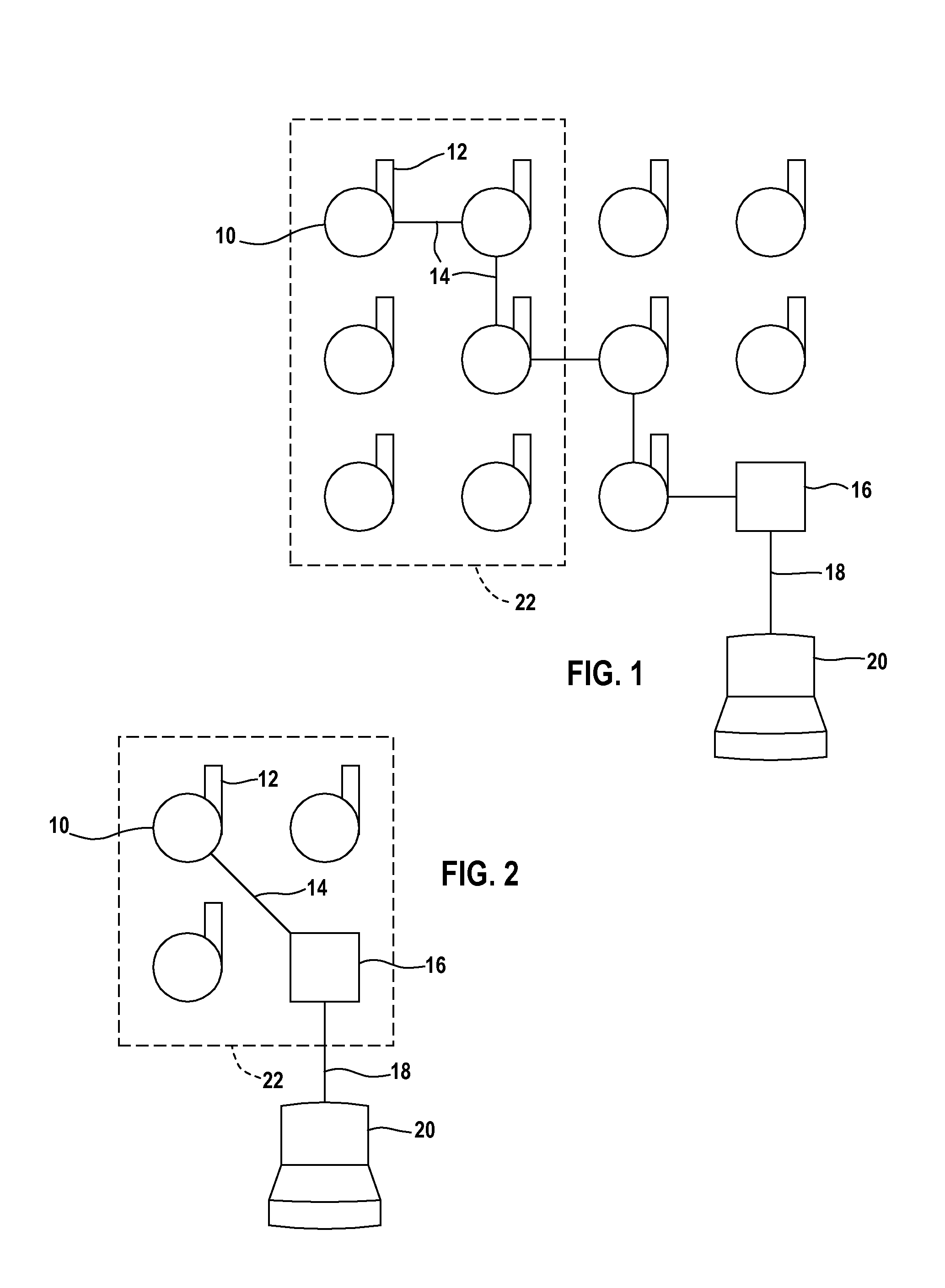
[0027]FIG. 1 illustrates a number of wireless field devices 10 in accordance with the present invention forming a self-organizing mesh network as is known in the distributed control system art. Each field device 10 forms a node on the network and includes a removable antenna assembly or module 12 that enables a field device 10 to receive or transmit radio frequency communications 14 through adjacent nodes to a gateway device 16. The gateway device 16 is conventional and connects the mesh network through a wired network connection 18 to a host 20.

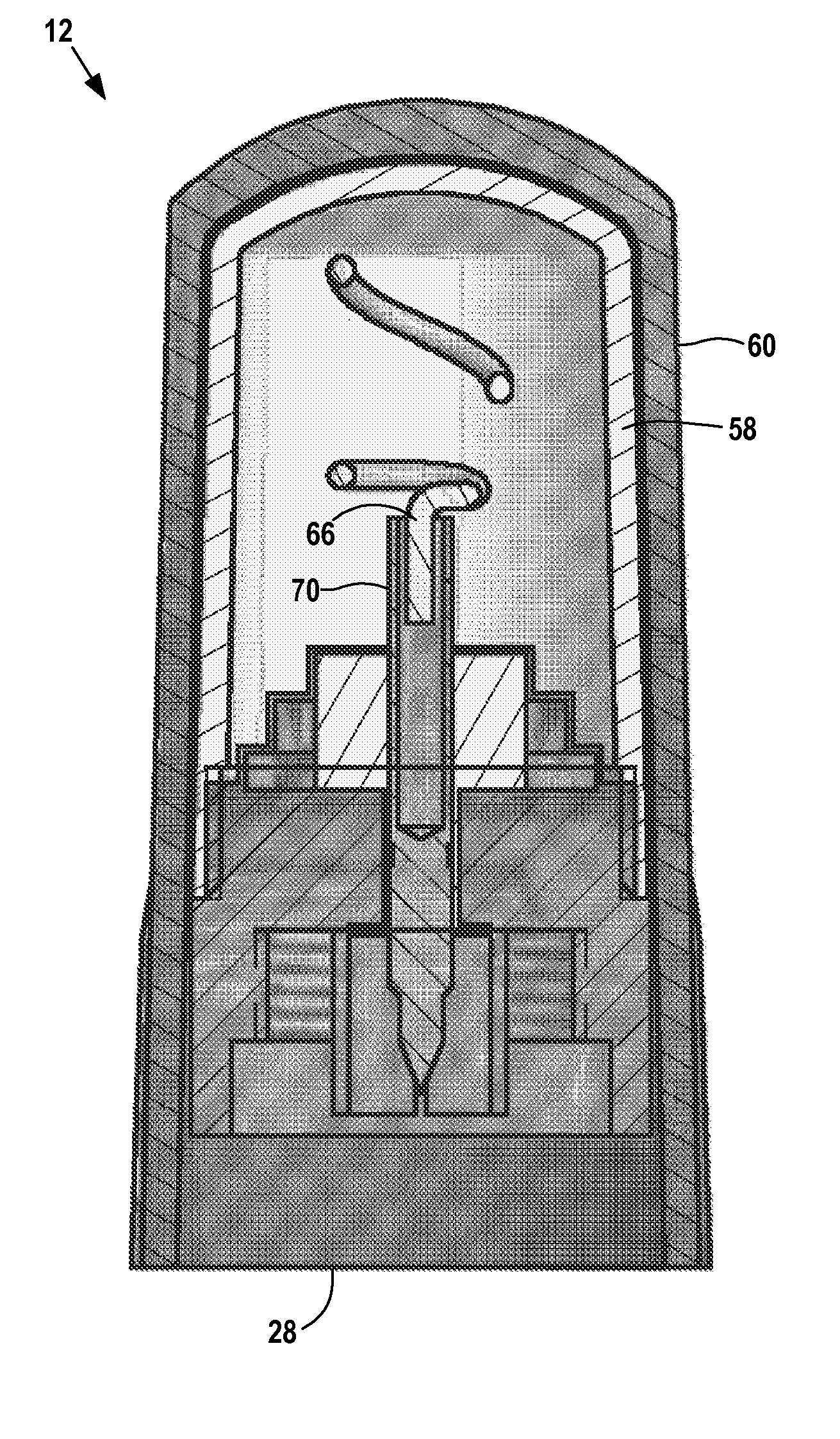
[0028]Some of the wireless field devices 10 are located in a hazardous (classified) location represented by the dashed rectangle 22. The hazardous (classified) location can be a flammable or explosive environment. As described in greater detail below, the antenna module 12 of a field device 10 resists sparking and can be removed and replaced in the field even if the field device 10 is located in the hazardous (classified) location 22.
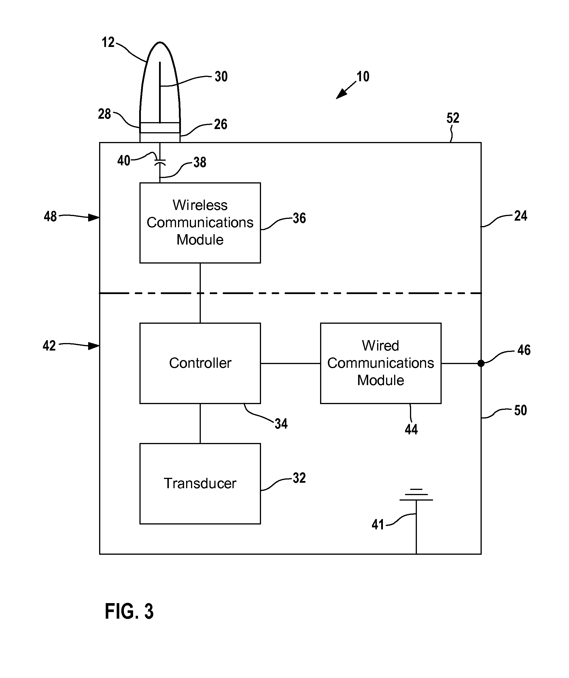
[0029]F...


PUM


Abstract

A wireless field device or an adapter for converting a wired field device to a wireless field device includes a housing, a first connector on the housing, and a removable antenna module that includes an antenna, a second connector coupleable and uncoupleable with the first connector, and a radome that houses the antenna and fits on the second connector. The radome is made of a static dissipative material that dissipates static buildup without sparking when coupling or uncoupling the connectors, enabling the antenna to be removed or replaced while the field wireless field device is located in a hazardous (classified) location.

Description


Claims


Application Information

Patent Timeline
Owner PHOENIX CONTACT DEVMENT & MFG
Why Eureka
Try Eureka