Pedal generator electric bicycle

a pedal generator and electric bicycle technology, applied in the field of transportation, can solve the problem of not allowing the charging of the battery

Inactive Publication Date: 2012-08-09
CLARKSON UNIVERSITY
View PDF17 Cites 57 Cited by
  • Summary
  • Abstract
  • Description
  • Claims
  • Application Information

AI Technical Summary

Benefits of technology

[0007]The present invention is a chainless electric cycle design that allows the user to pedal a pedal generator to create an electric transmission energy source that either charges the battery or partially powers a hub motor, discharges the battery to the hub motor contained within one of the wheels, allows the user to set a desired level of resistance from the pedal generator using controls oriented about the handlebars, allows the user to activate the hub motor using a speed controlling device oriented about the handlebars, and allows the user to charge the battery by connecting to a standard 110V / 220V AC power supply. A chainless cycle is a cycle where the input power from a rider is not converted into output power by the rear wheel through a gear and chain system connecting the pedals to the rear wheel. Further, a chainless cycle is a cycle that does not utilize a mechanical system to convert rider / user human input power into propulsive output power on the driven wheel, where the mechanical system is typically comprised of a gear driven by turning the pedals, a gear that drives the rear wheel of the cycle, and a chain that connects the two gears.

Problems solved by technology

Both of these categories of electric bicycles allow the user to power the bicycle solely by human power, although the weight of additional components typically makes this an undesirable condition.
Additionally, both of these categories of electric bicycles typically do not permit charging of the battery by means of pedaling.

Method used


Image

  • Pedal generator electric bicycle
  • Pedal generator electric bicycle
  • Pedal generator electric bicycle

Examples


Embodiment Construction

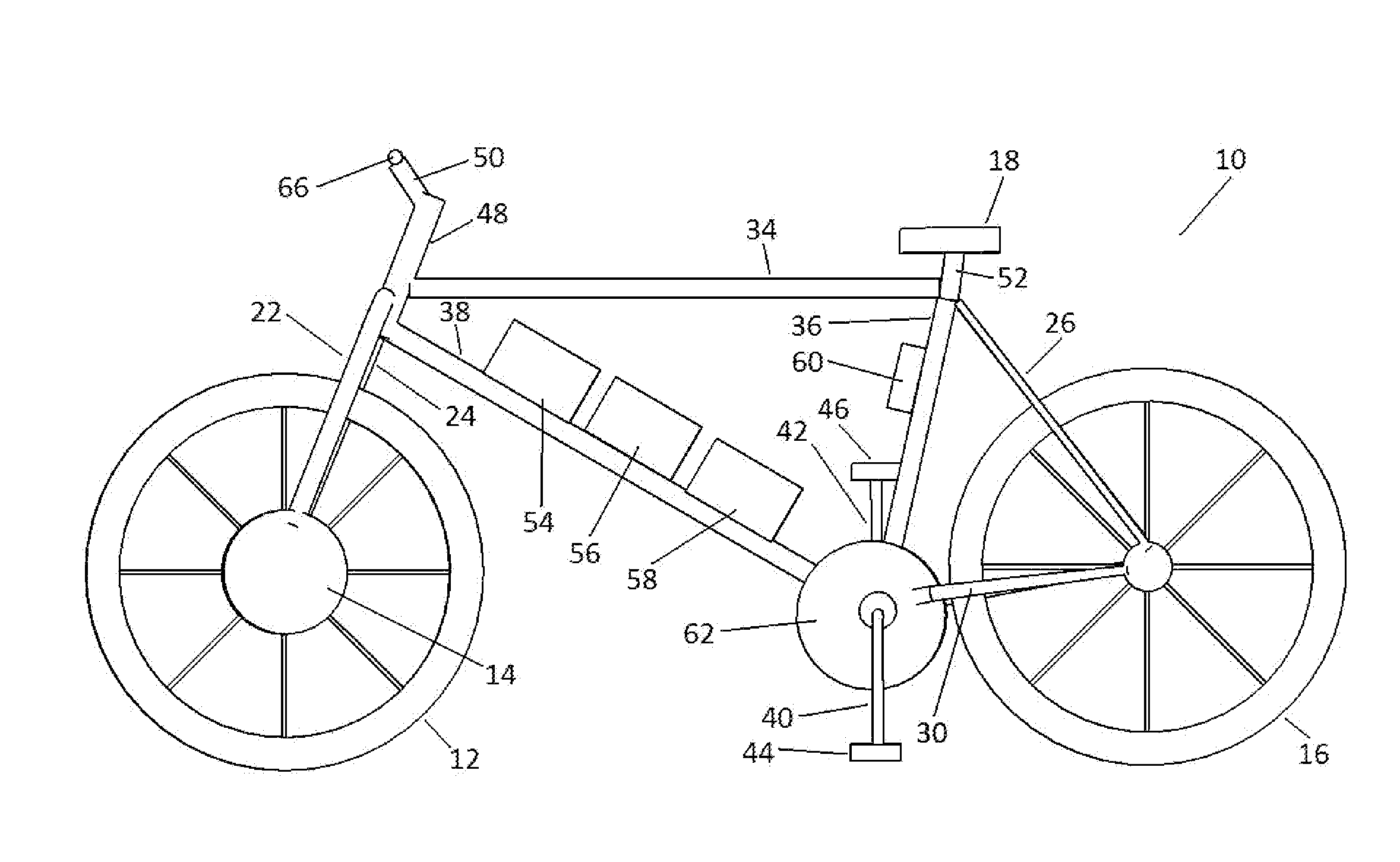
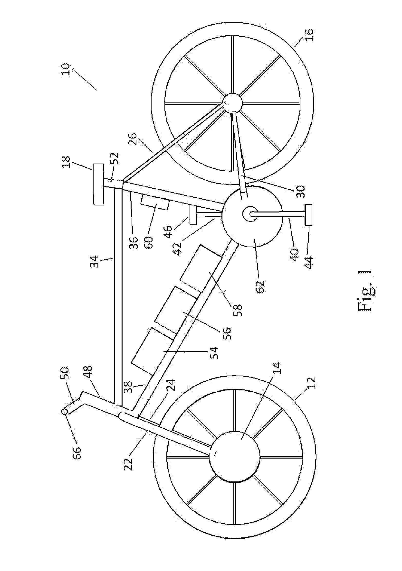
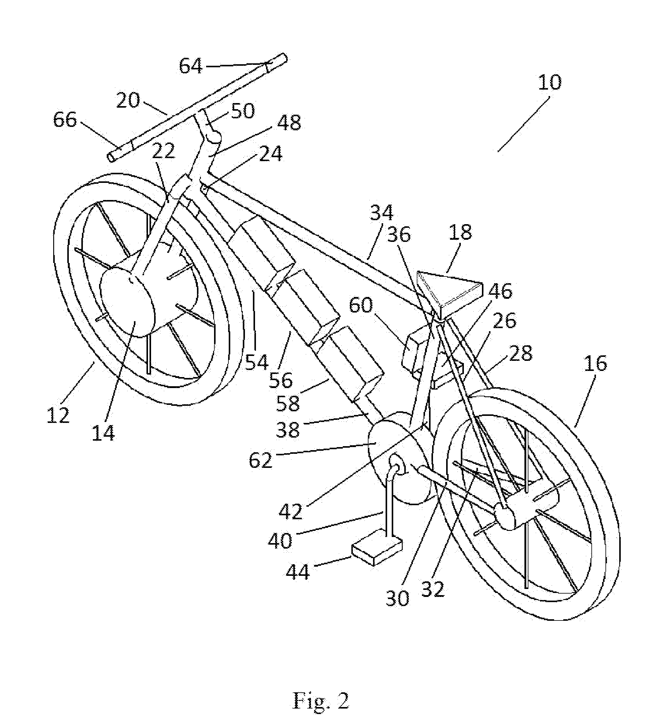
[0015]While the detailed description herein discloses a bicycle embodiment, the elements of the bicycle embodiment are relevant to other cycle embodiments disclosed further below. FIG. 1 and FIG. 2 illustrate a bicycle 10 having a front wheel 12 with a hub motor 14, a rear wheel 16, a seat 18, a set of handlebars 20, front wheel frame supports 22 and 24, rear wheel frame supports to a main triangular frame 26 and 28, a rear wheel frame that supports the pedal assembly 30 and 32, and a main triangular frame comprised of a top bar 34, a rear bar 36, and a front bar 38. The pedal assembly is comprised of pedal bars 40 and 42 and pedals 44 and 46. The front main bar 48 connects the front wheel frame supports, the main triangular frame, and the extension bar 50 to the handlebars 20. The rear top bar 52 connects the seat 18 to the main triangular frame. In addition to these common components of an electric bicycle, there are one or more (an exemplary value of three batteries 54, 56, and 5...


PUM


Abstract

A chainless electric cycle design that allows a rider / user to pedal a pedal generator to create an electric transmission energy source that either charges the battery or partially powers a hub motor, discharges the battery to the hub motor contained within one of the wheels, allows the user to set a desired level of resistance from the pedal generator using controls oriented about the handlebars, allows the user to activate the hub motor using a speed controlling device oriented about the handlebars, and allows the user to charge the battery by connecting to a standard 110V / 220V AC power supply. A chainless cycle is a cycle where the input power from a rider is not converted into output power by the rear wheel through a gear and chain system connecting the pedals to the rear wheel.

Description

CROSS-REFERENCE TO RELATED APPLICATIONS[0001]This is application is related to provisional application 61 / 440,000 filed on Feb. 7, 2011 entitled Concept Electric Bicycle and hereby incorporated herein by reference.BACKGROUND OF THE INVENTION[0002]The present invention is in the technical field of transportation. More particularly, the present invention is in the technical field of electric bicycle transportation.[0003]Existing electric bicycles typically fall into one of two categories. The first category includes electric bicycles that require the user to pedal before electric assistance is provided. These bicycles typically measure the amount of force the user is providing, through a conventional gear-and-chain system connecting the user's pedaling force with the rear wheel of the bicycle, and produce a multiple of that amount of force from an electric motor. The second category includes electric bicycles that do not require the user to pedal at all. These bicycles typically allow...

Claims


Application Information

Patent Timeline
Patent Type & Authority Applications(United States)
IPC IPC(8): A63B71/00
CPCA63B69/16B62M6/90B62M6/40
Inventor HUBER, MARK R.
Owner CLARKSON UNIVERSITY
Why Eureka
Try Eureka