Drum brake type parking brake apparatus

a technology of parking brakes and drum brakes, which is applied in mechanical devices, brake systems, transportation and packaging, etc., can solve the problems of reducing the size and weight of the drum brake type of parking brake apparatus, and achieves the effects of small output, reduced size and weight, and low transmission loss

Inactive Publication Date: 2012-08-16
AKEBONO BRAKE IND CO LTD
View PDF0 Cites 21 Cited by
  • Summary
  • Abstract
  • Description
  • Claims
  • Application Information

AI Technical Summary

Benefits of technology

[0051]The drum brake type parking brake apparatus of the present invention constituted as mentioned above is operated as below to exhibit the braking force. Upon braking, the proximal end portions of the pair of expansion levers are strongly clamped from opposite sides by the driving device, both expansion levers are oscillated and displaced around the pivot portion between both expansion levers and both end portions of the joining link, whereby the gap between the distal end portions of both expansion levers is expanded. Since the oscillation centers of both expansion levers are biased to the respective distal end sides as the output sides, the gap between the distal end portions of both expansion levers is expanded by a large force. Moreover, the distal end portion of the first expansion lever displaces the web of one brake shoe directly or via another member in the outer direction of the diameter direction, and the distal end portion of the second expansion lever displaces the web of the other brake shoe via the strut in the outer direction of the diameter direction, respectively. Moreover, the linings of both brake shoes are pushed to the inner peripheral surface of the drum, thereby performing the braking.
[0052]Along with the braking, the reaction is applied to the distal end portions of both of the expansion levers in the direction in which they approach each other. The reaction is applied to the joining link as force of a compression direction and is offset in the joining link. Furthermore, force applied from the driving device to the proximal end portions of both expansion levers is also applied to the joining link as force of the compression direction and is offset in the joining link. Thus, a large force due to the braking is not applied to the portion such as the back plate supporting the driving device.
[0053]According to the drum brake type parking brake apparatus of the present invention that is constituted as mentioned above and is operated as described above, by adopting the link type of force increasing device with a low transmission loss, it is possible to promote a reduction in size and weight using the electric motor having a relatively small output. In addition, it is possible to realize a structure in which a large force is not applied to the joining portion of the expansion and contraction device and the back plate by offsetting the reaction due to the braking in the expansion and contraction device. For example, if the joining link and both expansion levers also have sufficient strength and rigidity, there is no need to make the strength and rigidity of the portion such as the back plate supporting the driving device large. As a result, it is easy to promote a reduction in the weight of the drum brake type parking brake apparatus.
[0054]Furthermore, similar to the fifth invention, when the lever ratios of the first and second expansion levers are identical to each other, even if the positional relationship between both expansion levers and a pair of pressing members constituting the driving device is changed, the braking force is maintained at nearly the original size.
[0055]That is, the pair of brake shoes following the inner peripheral surface of the drum is sometimes displaced with respect to the back plate by an eccentric movement or the like of the drum. When such a displacement occurs, the distal end portions of both expansion levers engaged with the webs of both brake shoes are displaced, and both expansion levers are oscillated around the pivot portion between the expansion levers and the joining link in the same direction. In the case of the fifth invention, since the lever ratios of both of the expansion levers are substantially equal to each other, before and after the oscillation change of both expansion levers, the gap between the proximal end portions of both expansion levers is not changed. For this reason, even when the gap between the pair of pressing members is left as it is, force by which the distal end portions of both expansion levers press the webs of both brake shoes is not changed, and the driving force is maintained at nearly the original size.
[0056]In addition, according to a sixth invention, in the state in which the driving source such as the electric motor is fixed, the oscillation displacements of the pair of pressing members can be stably performed, whereby the structure is simplified and a reduction in cost is promoted.

Problems solved by technology

For this reason, there is a need to sufficiently raise the rigidity of a portion which supports and fixes the actuator 22 to the back plate 1, which is disadvantageous in terms of promoting a reduction in the size and weight of the drum brake type of parking brake apparatus.
For this reason, it is disadvantageous from the viewpoint of securing a deceleration ratio of the decelerator by effectively using the space of the rear surface side of the back plate 1, increasing the output of the actuator, and realizing a structure that promotes to secure the braking force.

Method used


Image

  • Drum brake type parking brake apparatus
  • Drum brake type parking brake apparatus
  • Drum brake type parking brake apparatus

Examples


first example of embodiment

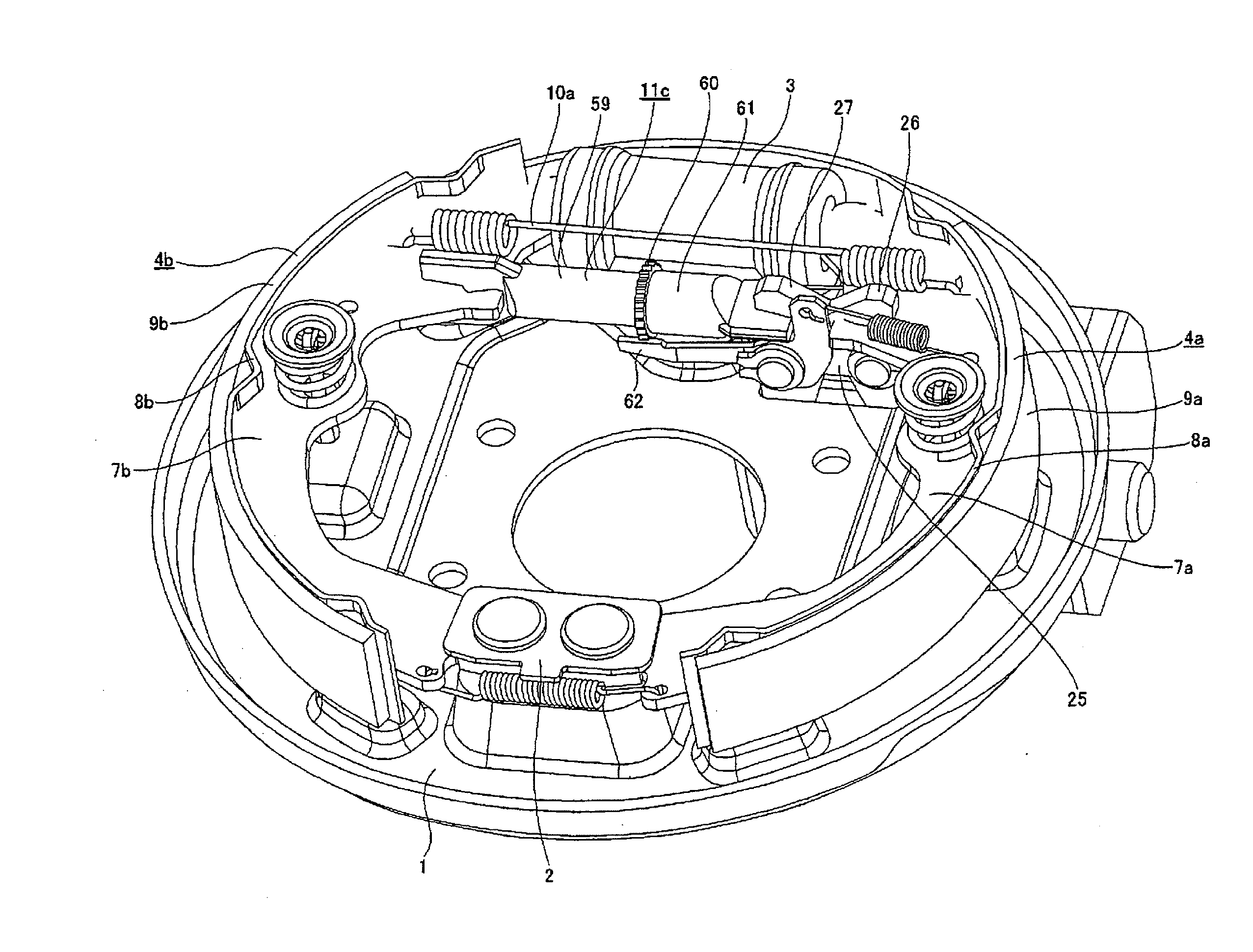
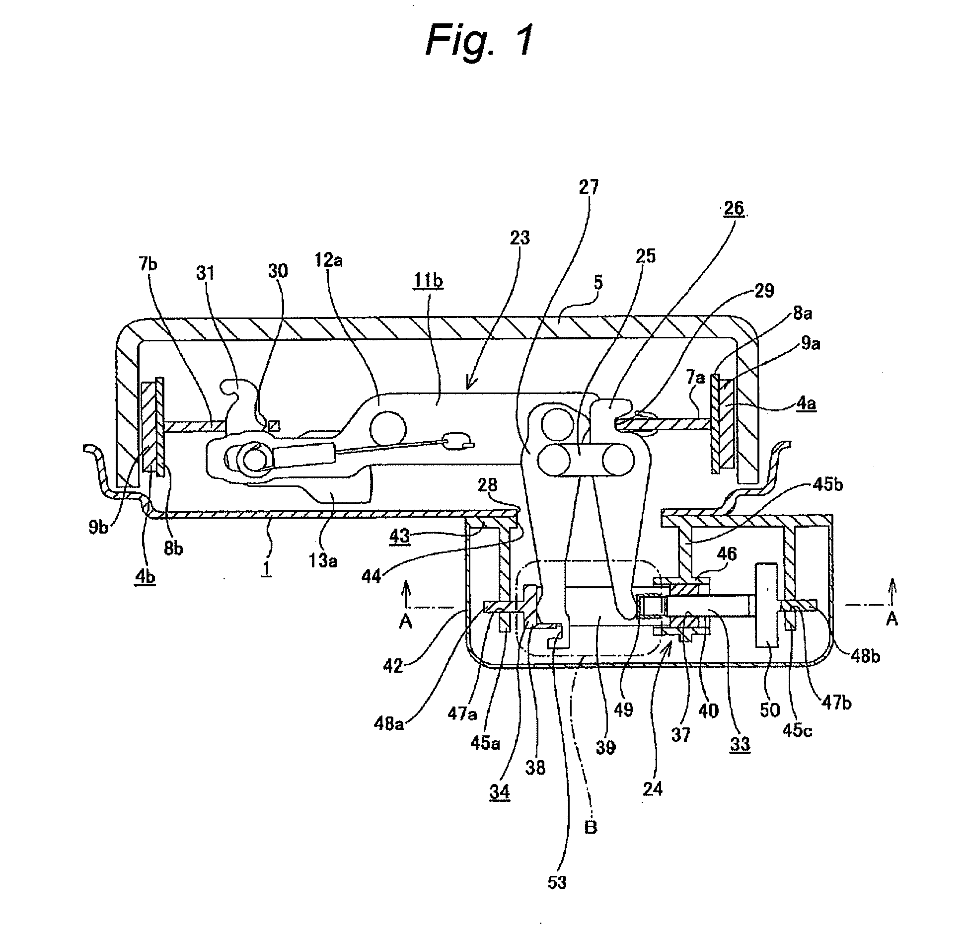
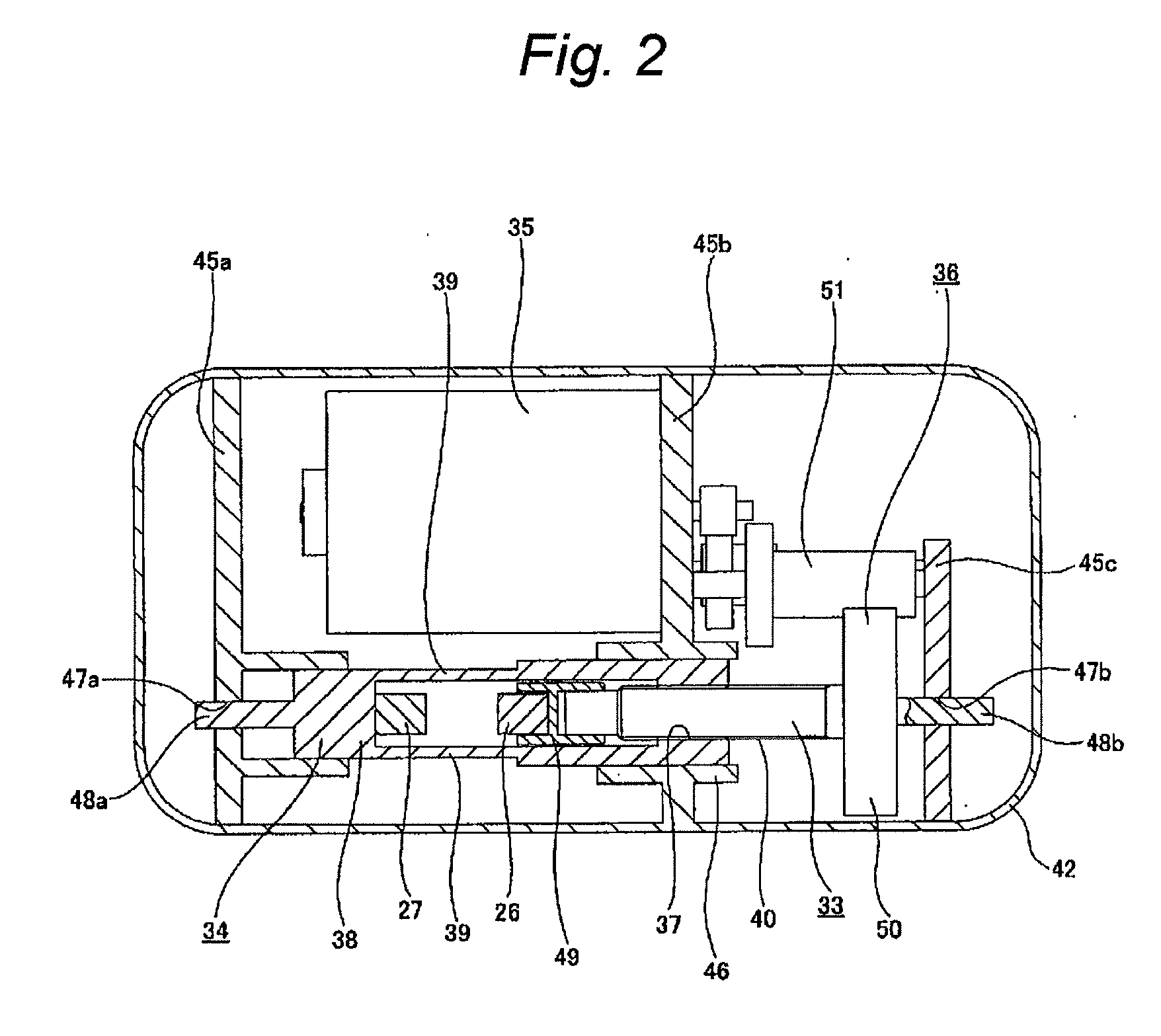
[0077]FIGS. 1 to 5 show a first example of an embodiment of the present invention corresponding to first to third, fifth and sixth inventions. Furthermore, a characteristic of the present invention including the present embodiment is a structure of a parking brake apparatus for a drum brake. Since a structure and an operation of a drum brake main body portion other than the parking brake device is identical to a leading and trailing type of drum brake widely known from the related art including the structure of the related art shown in aforementioned FIGS. 15 to 20, the illustrations and description relating to the identical portions will be omitted or simplified. Hereinafter, characteristic portions of the present invention will be preponderantly described.

[0078]An expansion and contraction device 23 for expanding and contracting a gap between a pair of brake shoes 4a and 4b is provided between inner peripheral edges of webs 7a and 7b constituting both of the brake shoes 4a and 4b,...

second example of embodiment

[0099]FIGS. 6 to 9 show a second example of an embodiment of the present invention corresponding to the first, fourth and fifth inventions. In the case of the present example, the first and second pressing members, which mutually clamp and press the proximal end portions of the first and second expansion levers 26 and 27 from the opposite sides, are a cover 42a fixed to the back plate 1, and a screw lever 54 supported in the cover 42a so as to be oscillatable only in the axial direction. Furthermore, the screw lever 54 is screwed into a screw hole 56 provided in a central portion of a deceleration rotation member 55 such as a large deceleration gear and a large deceleration pulley rotatably supported in the cover 42a. Furthermore, the deceleration rotation member 55 is freely rotated and driven via a belt 57 or a gear row by means of the electric motor constituting a driving source. Moreover, the proximal end portions of the first and second expansion levers 26 and 27 are mutually s...

third example of embodiment

[0102]FIGS. 10 and 11 show a third example of an embodiment of the present invention corresponding to the first to third, fifth and sixth inventions. In the case of the present example, in contrast to the case of the first example of the aforementioned embodiment, the female screw portion 37a is provided on the side of the second pressing member 33a, the male screw portion 40a is provided on the side of the first pressing member 34a, respectively, and both of the screw portions 37a and 40a are screwed into each other. Moreover, in order to mutually clamp the proximal end portions of the first and second expansion levers 26a and 27a from opposite sides and enable the proximal end portions to be pressed by both of the pressing member 33a and 34a, pressing target plate portions 64a and 64b are provided in the side edge portions of the portions near the proximal ends of both expansion levers 26a and 27a, respectively. Both of the pressing target plate portions 64a and 64b are formed by ...


PUM


Abstract

A joining link, a strut, and first and second expansion levers constitute an expansion and contraction device. At the time of the braking, the proximal end portion of both of the expansion levers are mutually pressed from the opposite sides by first and second pressing members constituting a driving device. The reaction due to the braking is offset by the joining link portion, whereby a large force is not applied to the back plate or the like.

Description

TECHNICAL FIELD[0001]The present invention is related to an improvement in drum brake type parking brake apparatus for maintaining a vehicle (automobile) in a stop state.BACKGROUND ART[0002]In order to perform the braking of a vehicle, a drum brake is widely used. In the drum brake, for example, as described in NPL 1, various types of drum brakes are known. Among them, a leading and trailing type of drum brake is widely used, since it obtains stable braking force upon forward movement and upon reverse movement. FIGS. 15 to 17 show an example of a leading and trailing type of drum gear disclosed in PTL 1. The drum brake includes a back plate 1, an anchor 2, a wheel cylinder 3, a pair of brake shoes 4a and 4b, and a drum 5.[0003]Among them, the back plate 1 is supported and fixed to constituent members of a suspension device such as a knuckle and an axle housing. Furthermore, the anchor 2 is supported and fixed to a portion near the outside of one circumferential direction of one plac...

Claims


Application Information

Patent Timeline
Patent Type & Authority Applications(United States)
IPC IPC(8): F16D51/22F16D65/22B60T1/06
CPCF16D51/20F16D65/563F16D65/58F16D2121/02F16D2121/14F16D2125/68F16D2123/00F16D2125/48F16D2125/52F16D2125/565F16D2125/64F16D2121/24
Inventor TSUZUKU, HARUOISHIKAWA, HIROYASUIKEGAMI, HIROSHIKAKIZAKI, HIDEKIMAEHARA, TOSHIFUMI
Owner AKEBONO BRAKE IND CO LTD
Why Eureka
Try Eureka