Image forming apparatus

Active Publication Date: 2012-08-16
CANON KK
View PDF1 Cites 13 Cited by
  • Summary
  • Abstract
  • Description
  • Claims
  • Application Information

AI Technical Summary

Benefits of technology

[0009]The disclosure provides an image forming apparatus configured in such a manner that even when a recording material comes int

Problems solved by technology

When the leading end of the recording material is at the transfer nip portion, the recording material vibrates due to a shock imparted by a contact to other portions of the trailing end of the recording material caused by the change of the posture of the recording material, which may cause a transfer failure.
When the leading end of the recording material comes into contact with the intermediate transfer belt, there is a case where an impact is propagated to the transfer nip porti

Method used


Image

  • Image forming apparatus
  • Image forming apparatus
  • Image forming apparatus

Examples


embodiment

Image Forming Apparatus

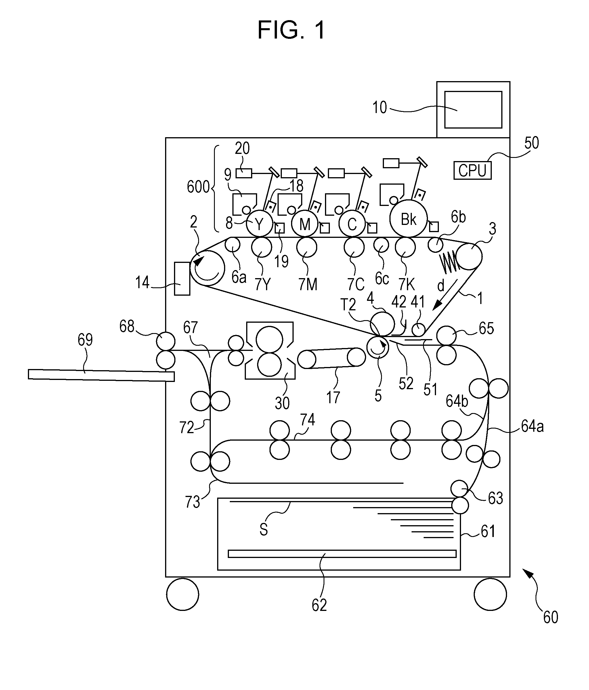
[0014]An image forming apparatus according to an embodiment of the disclosure will be described. FIG. 1 is a cross-sectional view of a color image forming apparatus using an electrographic system. An image forming apparatus 60 includes image forming portions configured to form images using toner of four different colors, respectively, arranged side by side so as to oppose an intermediate transfer belt 1.

Process of Conveying Recording Material

[0015]First of all, a process of conveying recording materials in an image forming apparatus shown in FIG. 1 will be described. Recording materials S are accommodated in a state of being stuck in a lift up apparatus 62 in a recording material storage 61, and are supplied by a paper feeder 63 at timing preset so as to coincide with image forming timing. Here, the paper feeder 63 in this embodiment employs a system using a frictional separation using a paper supply roller or the like. The recording material S supplied by the...


PUM


Abstract

An area in which a sheet member and an intermediate transfer belt are in contact with each other is provided between an intersection between a guide surface of the second guide portion configured to guide a recording material toward the intermediate transfer belt and the intermediate transfer belt and a nip portion.

Description

BACKGROUND[0001]1. Field of the Invention[0002]The present disclosure relates to an image forming apparatus such as copying machines, printers, and facsimile apparatuses configured to form a toner image on a recording material using an electrophotographic system or an electrostatic recording system. More specifically, the disclosure relates to an image forming apparatus having an intermediate transfer belt configured to carry a toner image to be transferred to a recording material.[0003]2. Description of the Related Art[0004]Examples of image forming apparatuses of the related art include a configuration in which a toner image formed on a photosensitive drum as an image carrier is transferred to a recording material at a transfer nip portion.[0005]At the time of conveying the high-rigidity recording material such as a thick paper, when a trailing end of the recording material leaves a covey roller or a leading end of the recording material enters the transfer nip portion, the postur...

Claims


Application Information

Patent Timeline
IPC IPC(8): G03G15/20
CPCG03G15/161G03G15/1605G03G2215/0141
Inventor NAKAJIMA, TAKAO
Owner CANON KK
Why Eureka
Try Eureka