Feeder element

a technology of feeder sleeve and feeder plate, which is applied in the field of feeder element, can solve the problems of shrinkage defects in casting, difficult to retain the position of the feeder sleeve on the swing plate during normal movements, and inability to simply use a larger standard shaped feeder, etc., to achieve the effect of preventing deformation, and reducing the risk of shrinkage defects

Active Publication Date: 2012-08-23
FOSECO INT LTD
View PDF3 Cites 19 Cited by
  • Summary
  • Abstract
  • Description
  • Claims
  • Application Information

AI Technical Summary

Benefits of technology

[0030]Embodiments of the present aspect of the invention can therefore provide an asymmetrical feeder element that is suitable for use in high pressure vertically parted mould machines (such as those manufactured by DISA Industries A/S). As described above, it can be advantageous to use asymmetric feeder sleeves such that in use there is an increased height above the bore axis. This provides for a greater volume of metal and ferrostatic (head) pressure above the bore axis and feeder neck to ensure a greater and more efficient flow of molten metal into a mould cavity. The Applicants therefore decided to trial open-sided sleeves (instead of providing a lower neck down portion) such that the feeder element was provided on a mounting plate arranged to abut the edge of the sleeve's open-side. Thus, feeder elements such as those described in WO2005/051568 and WO2007/141466 were simply provided on elongate mounting plates for use on elongate sleeves. However, it was discovered that when high mould pressure was applied to these components, the compressible part of the feeder element collapsed as required, however, the forces absorbed and transmitted through the collapsible part and into the moulding plate caused the portion of the feeder element in contact with the sleeve to unexpectedly buckle and bend outwardly from the sleeve. This was not satisfactory because it could allow molten metal to escape from parts of the feeder sleeve other than the bore, which could, in turn, affect the casting quality and efficiency. It was therefore desirable to design a feeder element which included a collapsible...

Problems solved by technology

Due to space restrictions and yield requirements, it is not practical to simply use a larger standard shaped (i.e. circular cross-sectional or symmetrical) feeder.
The sleeve body itself was circular, with a flat closed top, however, it was difficult to retain the position of the feeder sleeve on the swing (pattern) plate during the normal movements of the swing plate in the mould making cycle.
However, on casting, there was insufficient feeding of the casting, resulting in shrinkage defects being formed in the casting.
This improved the feed performance by increasing the ferrostatic pressure, but not enough to produce a defect free casting.
It was not possib...

Method used


Image

  • Feeder element
  • Feeder element
  • Feeder element

Examples


examples

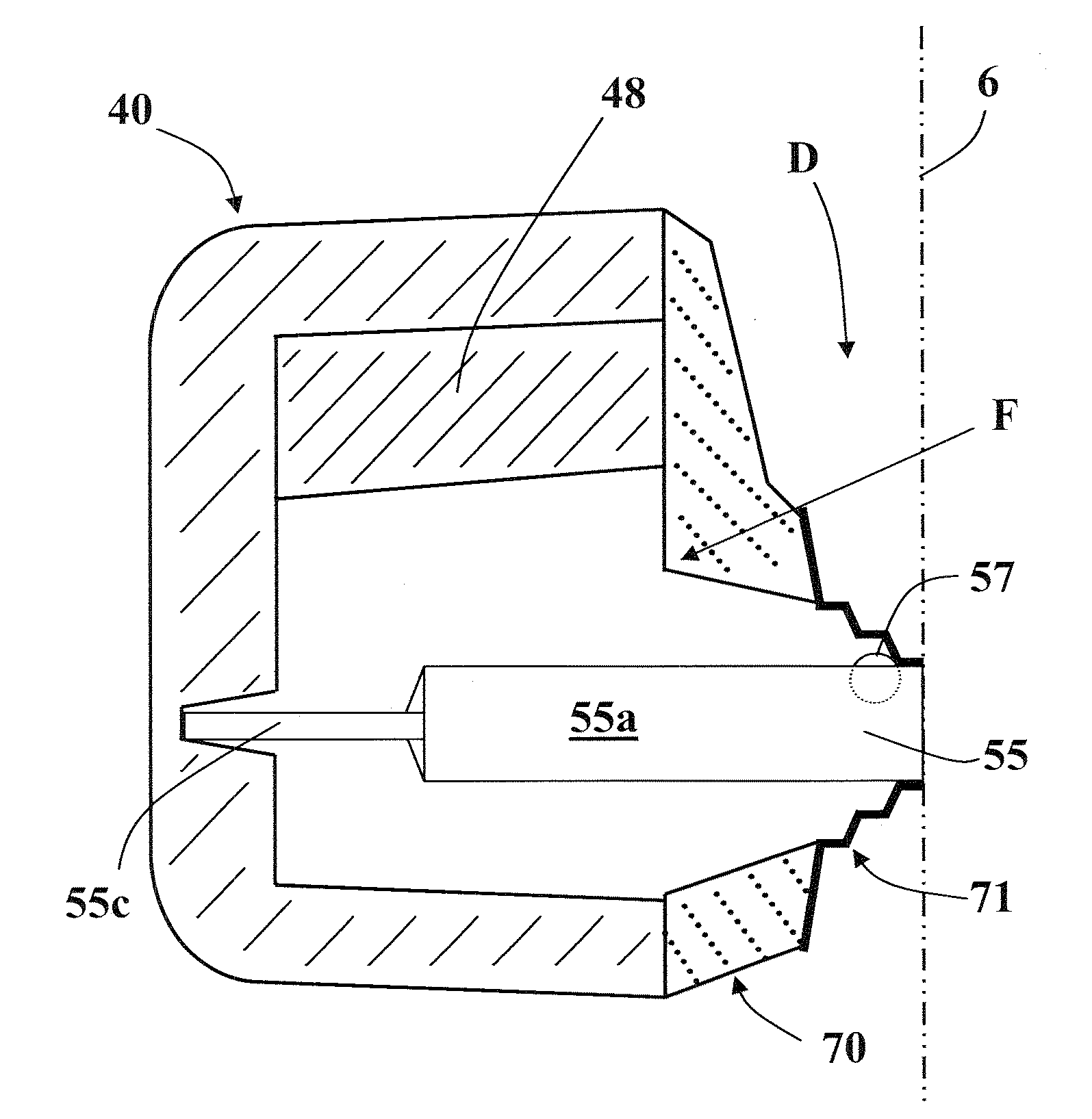
[0117]Various feeder systems were prepared using the feeder sleeve 40 as in FIG. 3, in combination with various feeder elements, and moulded as described above. The KALMINEX feeder sleeve had the dimensions 90 mm length×60 mm width×60 mm depth, where the length and width are the dimensions of the open face, and the depth of the feeder was measured from the open face to the closed back wall of the feeder.

[0118]The results are summarised in Tables 1a and 1b below.

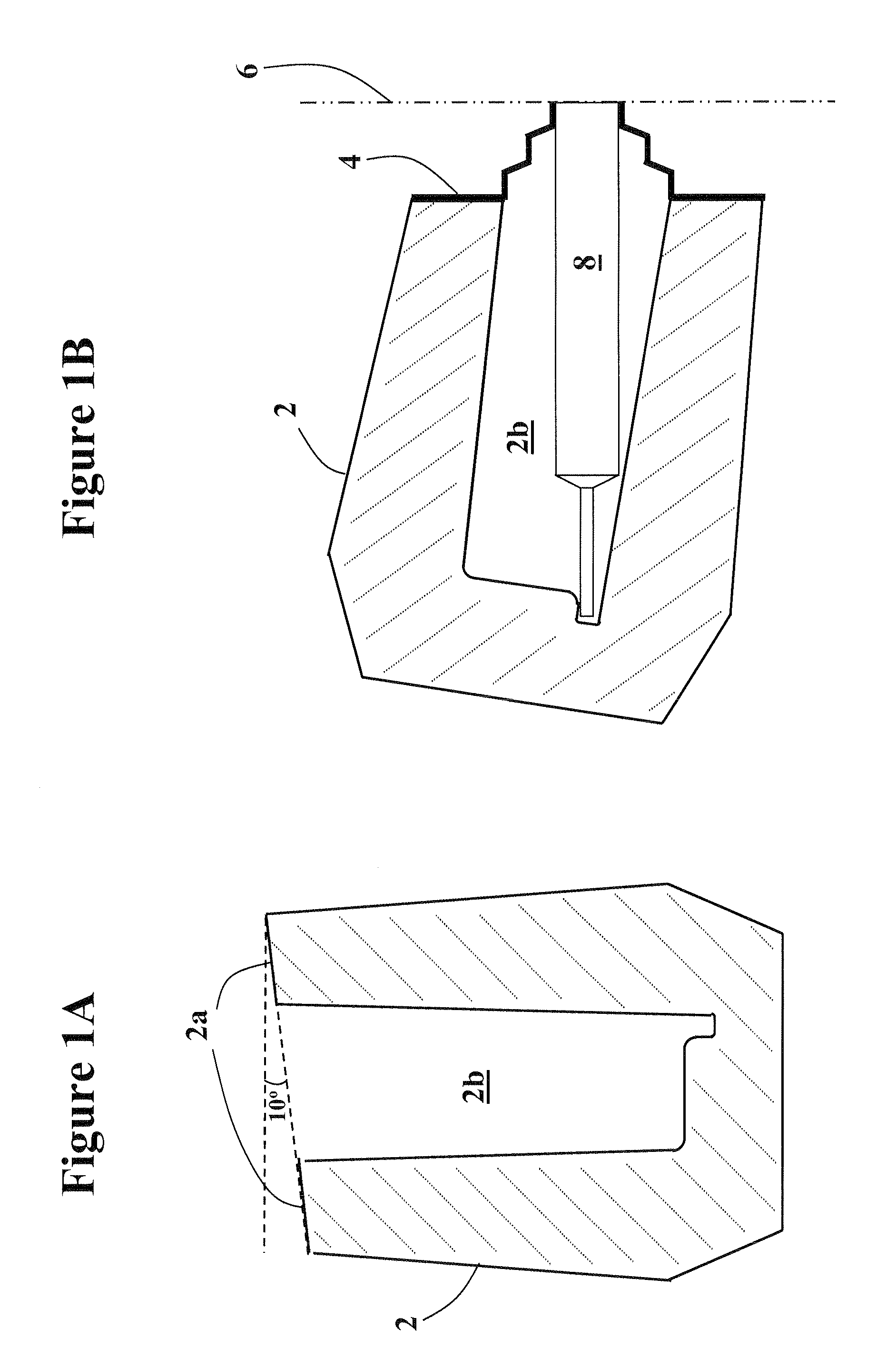
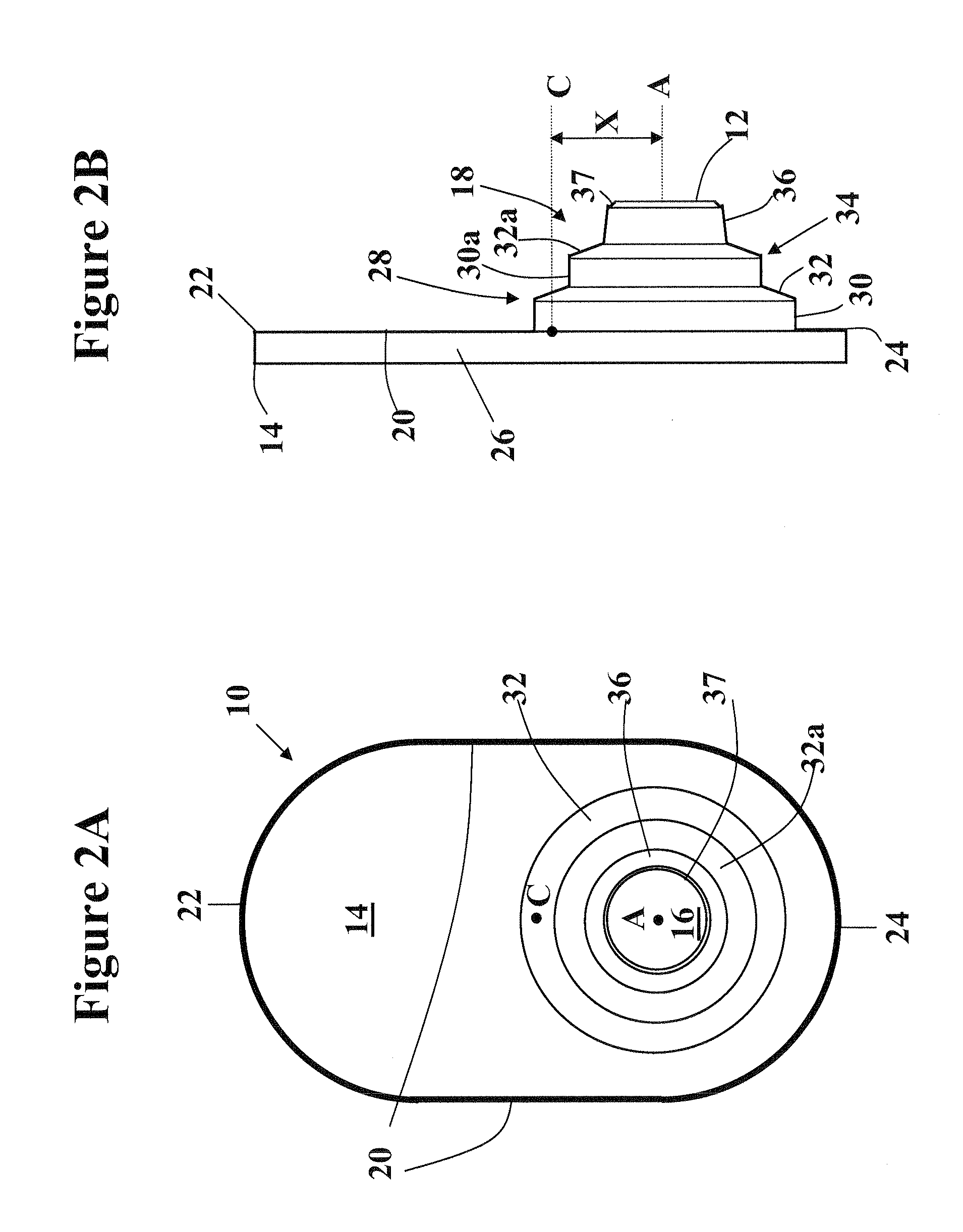
TABLE 1aFeeder Element DetailsBoreBore OffsetRimRimFeeder SystemElement Type / DesignDiameter(HC)Rim Type / DesignWidthAngleComparative 1Resin bonded sand25 mm15 mmNonen / an / aDesign as in FIG. 6Comparative 2Resin bonded sand18 mm15 mmNonen / an / aneck down plus 0.5 mmsteel, circular compressible.Design as in FIG. 7Comparative 30.5 mm steel, obround,18 mm15 mmNonen / an / acompressible Design asin FIG. 8Comparative 40.5 mm steel, obround,18 mm15 mmNonen / an / acompressible Design asin FIGS. 10A / BExample 10.5 mm steel obround18 mm15 mmContinu...


PUM


Abstract

The present invention relates to a feeder element for use in metal casting. The feeder element comprises a first end for mounting on a mould pattern or swing plate, an opposite second end comprising a mounting plate for mounting on a feeder sleeve and a bore between the first and second ends defined by a sidewall. The feeder element is compressible in use whereby to reduce the distance between the first and second ends. The bore has an axis that is offset from the centre of the mounting plate and an integrally formed rim extends from a periphery of said mounting plate.
The feeder element of the invention finds particular utility in high pressure vertically parted sand moulding systems.

Description

FIELD OF THE INVENTION[0001]The present invention relates to a feeder element for use in metal casting operations utilising casting moulds, especially but not exclusively in high pressure vertically parted sand moulding systems.BACKGROUND[0002]In a typical casting process, molten metal is poured into a pre-formed mould cavity which defines the shape of the casting. However, as the metal solidifies it shrinks, resulting in shrinkage cavities which in turn result in unacceptable imperfections in the final casting. This is a well known problem in the casting industry and is addressed by the use of feeder sleeves or risers which are integrated into the mould during mould formation. Each feeder sleeve provides an additional (usually enclosed) volume or cavity which is in communication with the mould cavity, so that molten metal also enters into the feeder sleeve. During solidification, molten metal within the feeder sleeve flows back into the mould cavity to compensate for the shrinkage ...

Claims


Application Information

Patent Timeline
IPC IPC(8): B22C9/08
CPCB22C9/088B22C9/084B22C9/08
Inventor SALLSTROM, JANJEFFS, PAUL DAVID
Owner FOSECO INT LTD
Why Eureka
Try Eureka