Sealing device and method for providing a seal in a turbine system

a sealing device and turbine technology, applied in the field of turbine systems, can solve the problems of reducing the gap between adjacent components, and the further reduction of the performance, efficiency and power output of the turbine system

Inactive Publication Date: 2012-08-23
GENERAL ELECTRIC CO
View PDF24 Cites 24 Cited by
  • Summary
  • Abstract
  • Description
  • Claims
  • Application Information

AI Technical Summary

Benefits of technology

[0006]Aspects and advantages of the invention will be set forth in part in the following description, or may be obvious from the description, or may be learned through practice of the invention.

Problems solved by technology

Frequently, gaps exist between adjacent components.
These gaps may allow for leakage of the high temperature flows from the hot gas path, resulting in decreased performance, efficiency, and power output of the turbine system.
However, the gaps between adjacent components may allow for leakage of the cooling medium and mixing with the high temperature flows, resulting in further decreased performance, efficiency, and power output of the turbine system.
However, these sealing mechanisms, while preventing some leakage, may not adequately seal the gaps between adjacent components.

Method used


Image

  • Sealing device and method for providing a seal in a turbine system
  • Sealing device and method for providing a seal in a turbine system
  • Sealing device and method for providing a seal in a turbine system

Examples


Embodiment Construction

[0016]Reference now will be made in detail to embodiments of the invention, one or more examples of which are illustrated in the drawings. Each example is provided by way of explanation of the invention, not limitation of the invention. In fact, it will be apparent to those skilled in the art that various modifications and variations can be made in the present invention without departing from the scope or spirit of the invention. For instance, features illustrated or described as part of one embodiment can be used with another embodiment to yield a still further embodiment. Thus, it is intended that the present invention covers such modifications and variations as come within the scope of the appended claims and their equivalents.

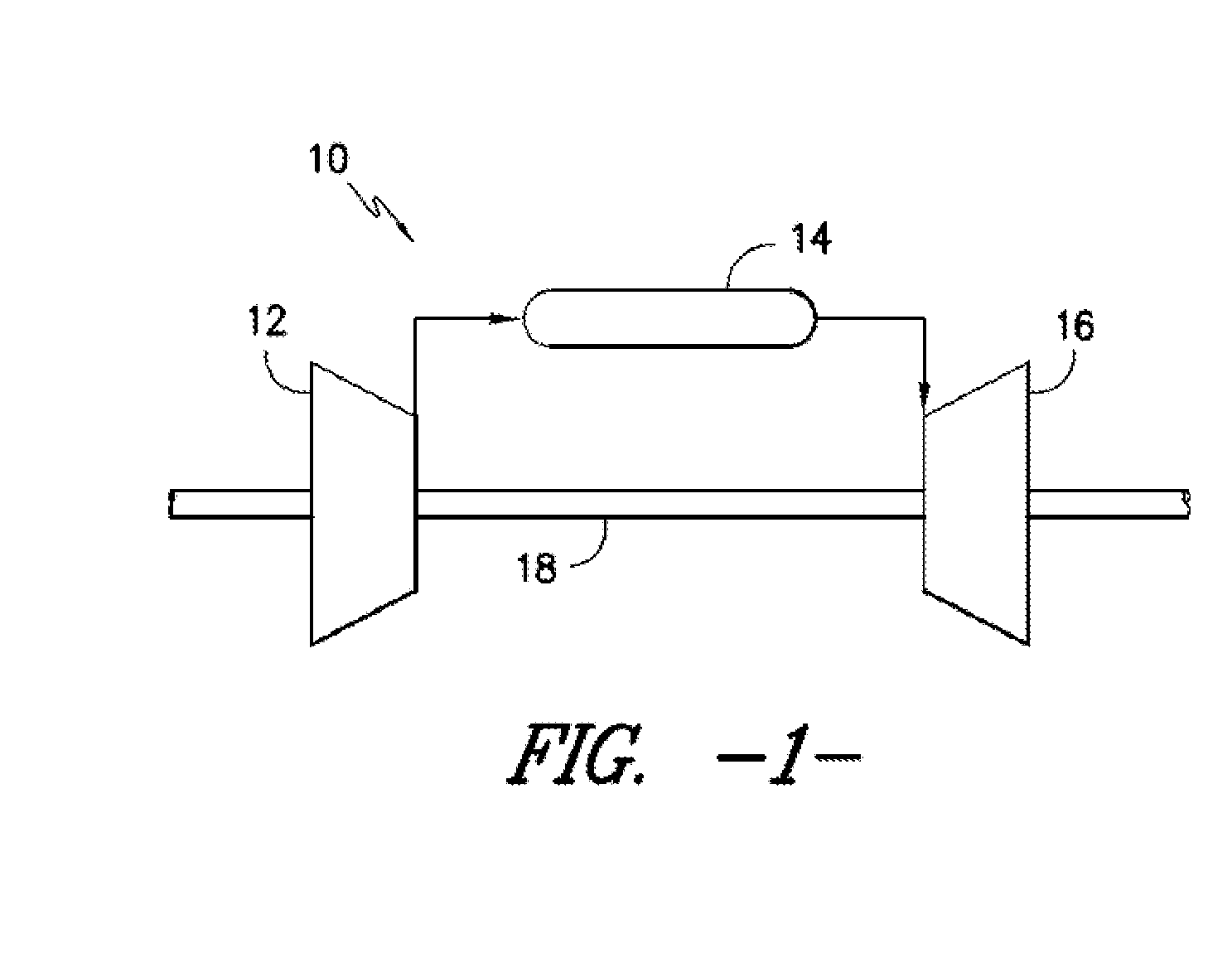
[0017]FIG. 1 is a schematic diagram of a gas turbine system 10. The system 10 may include a compressor 12, a combustor 14, and a turbine 16. Further, the system 10 may include a plurality of compressors 12, combustors 14, and turbines 16. The compressor 12 ...


PUM


Abstract

A sealing device and a method for providing a seal between adjacent components in a turbine system are disclosed. The sealing device includes a seal plate configured to provide a seal between adjacent components, a wire mesh mounted to the seal plate, the wire mesh defining a plurality of voids, and a sealant impregnating the wire mesh such that at least a portion of the plurality of voids include the sealant therein.

Description

FIELD OF THE INVENTION[0001]The present disclosure relates in general to a turbine system, and more particularly to sealing devices and methods for providing seals between adjacent components of a turbine system.BACKGROUND OF THE INVENTION[0002]Turbine systems are widely utilized in fields such as power generation. A conventional gas turbine system, for example, includes a compressor, a combustor, and a turbine. During operation of a turbine system, various components in the system are subjected to high temperature flows. Many of the components are disposed in annular arrays about an axis of the gas turbine system. Further, many of the components are positioned adjacent to other components, in annular arrays, radially, axially, or otherwise. For example, compressor and turbine blades, nozzles, and shroud blocks are positioned in annular arrays and are further positioned adjacent to each other. Frequently, gaps exist between adjacent components. These gaps may allow for leakage of th...

Claims


Application Information

Patent Timeline
Patent Type & Authority Applications(United States)
IPC IPC(8): F16J15/06
CPCF01D11/005F05D2240/57F01D11/008
Inventor HEFNER, REBECCA EVELYNHARDWICKE, CANAN USLUMORGAN, VICTOR JOHN
Owner GENERAL ELECTRIC CO
Why Eureka
Try Eureka