Device, system, and method for inductive charging

a technology of inductive charging and charging terminals, applied in the direction of inductance, battery data exchange, transportation and packaging, etc., can solve the problem that the inductive charging terminals may not match a specific specification, and achieve the effect of maximizing the transmission efficiency of electromagnetic induction

Inactive Publication Date: 2012-08-23
PANTECH CO LTD
View PDF6 Cites 65 Cited by
  • Summary
  • Abstract
  • Description
  • Claims
  • Application Information

AI Technical Summary

Benefits of technology

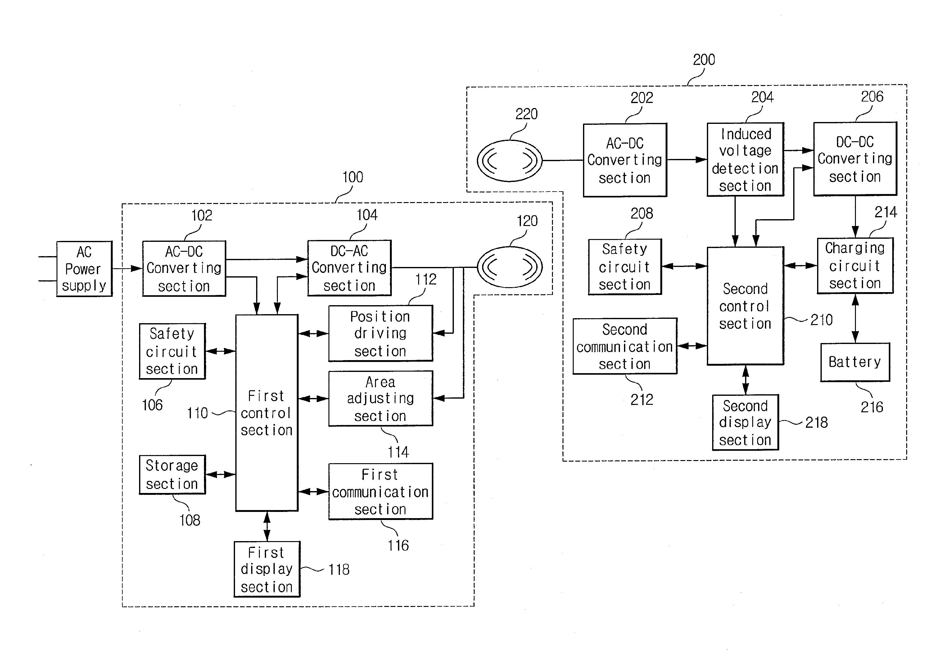
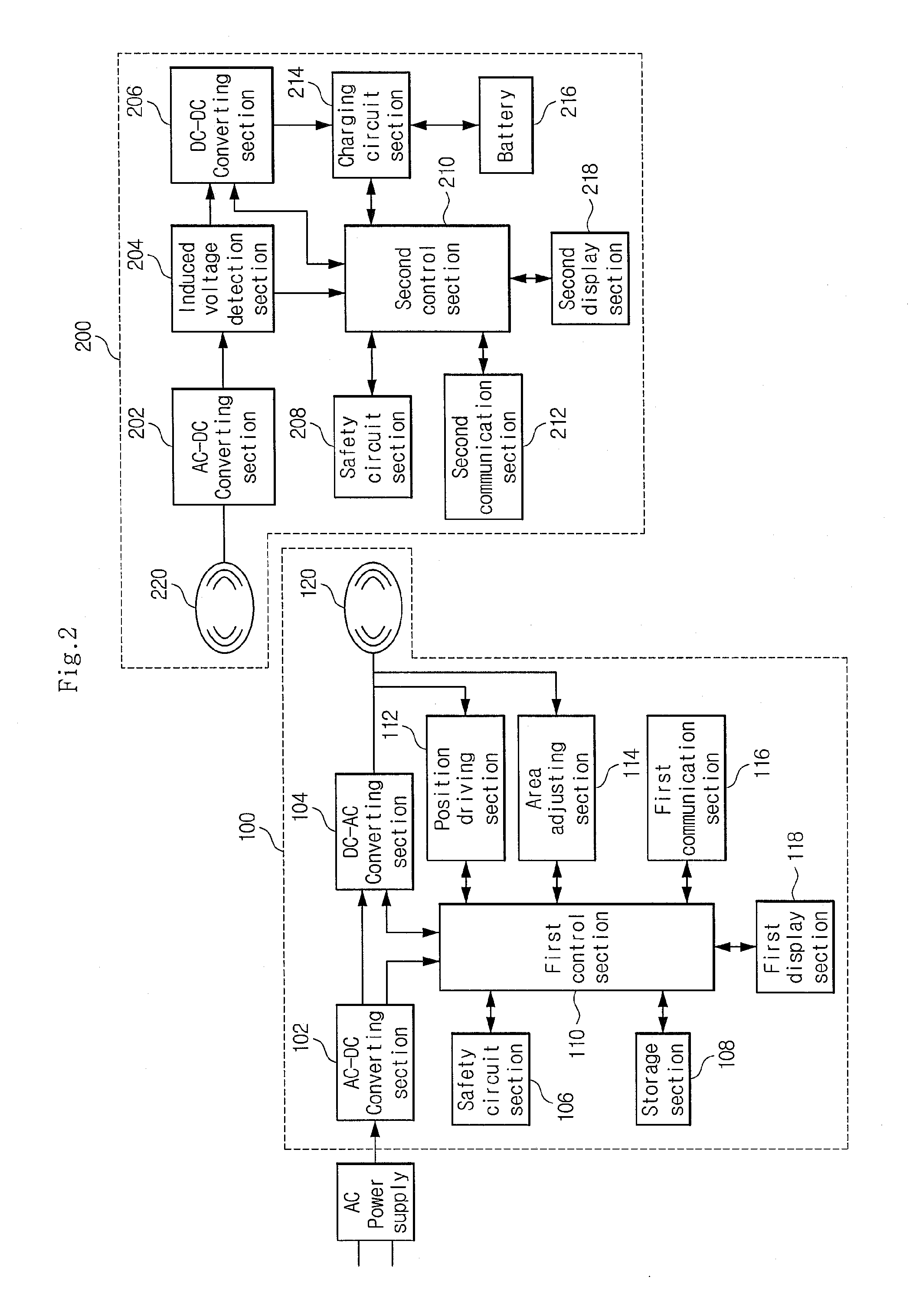
[0010]An exemplary embodiment provides an inductive charging device to supply power to a subject charging terminal, the device including: a primary coil to charge a secondary coil of the subject charging terminal through electromagnetic induction; a power supply section to supply induced current to the primary coil; and a first control section to control the supply of induced current and to change an attribute of the primary coil to maximize transmission efficiency of the electromagnetic induction.
[0011]An exemplary embodiment provides an inductive charging system, the system including: an inductive charging device to supply power to the subject charging terminal, the inductive charging device with a primary coil to produce electromagnetic induction, a power supply section to supply an induced current to the primary coil, and a first control section to control the power supply section; the subject charging terminal including: a secondary coil magnetically coupled to the primary coil and to generate an induced voltage, and a battery to receive the induced voltage, wherein the first control section changes an attribute of the primary coil to maximize transmission efficiency of the electromagnetic induction.

Problems solved by technology

However, the inductive charging terminal may not match a specific specification, since the capacity of the primary coil may not be configured for the secondary coil of the subject charging terminal.

Method used


Image

  • Device, system, and method for inductive charging
  • Device, system, and method for inductive charging
  • Device, system, and method for inductive charging

Examples


Embodiment Construction

[0024]The invention is described more fully hereinafter with reference to the accompanying drawings, in which exemplary embodiments of the invention are shown. This invention may, however, be embodied in many different forms and should not be construed as limited to the embodiments set forth herein. Rather, these exemplary embodiments are provided so that this disclosure is thorough, and will fully convey the scope of the invention to those skilled in the art. In the drawings, the size and relative sizes of layers and regions may be exaggerated for clarity. Like reference numerals in the drawings denote like elements.

[0025]The terminology used herein is for the purpose of describing particular embodiments only and is not intended to be limiting of the present disclosure. As used herein, the singular forms “a”, “an” and “the” are intended to include the plural forms as well, unless the context clearly indicates otherwise. Furthermore, the use of the terms a, an, etc. does not denote ...


PUM


Abstract

In a device system, and method for inductive charging, an efficiency of transmission of electromagnetic induced power may be maximized. Specifically, a control portion of a charging device may change an attribute, such as position or area, of a primary coil as to be more aligned with a secondary coil of to be charged device.

Description

CROSS-REFERENCE TO RELATED APPLICATION[0001]This application claims priority from and benefit under 35 U.S.C. §119(a) of Korean Patent Application No. 10-2011-0014187, filed on Feb. 17, 2011, which is incorporate by reference for all purposes as if fully set forth herein.BACKGROUND[0002]1. Field[0003]This disclosure relates to a device, a system, and a method for inductive charging.[0004]2. Discussion of the Background[0005]Mobile terminals, such as smart phones, internet telephone (IT) devices, personal digital assistants (PDA) and notebooks have become utilized at a higher frequency. Since these devices are mobile, a battery is attached thereto. The battery is charged by a charging device, with the battery being separated from the device, or the battery being attached to both the device and the charging device. An inductive or non-contact charging device has been developed. The inductive charging device wireles sly charges the battery of the mobile device using electromagnetic ind...

Claims


Application Information

Patent Timeline
Patent Type & Authority Applications(United States)
IPC IPC(8): H02J7/00
CPCH02J7/025H02J7/0008H02J7/00041H02J50/90H02J7/00047H02J50/80H02J50/10H01F38/14
Inventor KIM, JAE KI
Owner PANTECH CO LTD
Why Eureka
Try Eureka