Electric power supplying device, of a wireless electric power transmission apparatus and method for supplying electric power

a wireless electric power transmission and electric power technology, applied in the direction of reducing harmonics/ripples, transformers/inductances, ac networks, etc., can solve the problems of short power transmission distance and degraded power transmission efficiency of wireless power transmission systems, so as to maximize power transmission efficiency and reduce power loss , the effect of enhancing power transmission efficiency

Active Publication Date: 2015-04-16
SCRAMOGE TECH LTD
View PDF8 Cites 10 Cited by
  • Summary
  • Abstract
  • Description
  • Claims
  • Application Information

AI Technical Summary

Benefits of technology

[0012]According to the embodiment of the present invention, the power consumption preventing unit is provided in the wireless power transmission system, thereby reducing power loss occurring when DC power is converted into AC power to maximize power transmission efficiency.
[0013]In addition, the power transmission efficiency ca

Problems solved by technology

Although the commercialization of the electromagnetic induction technology has been rapidly progressed around small-size devices, the power transmission distance thereof is short.
However, the power t

Method used


Image

  • Electric power supplying device, of a wireless electric power transmission apparatus and method for supplying electric power
  • Electric power supplying device, of a wireless electric power transmission apparatus and method for supplying electric power
  • Electric power supplying device, of a wireless electric power transmission apparatus and method for supplying electric power

Examples


first embodiment

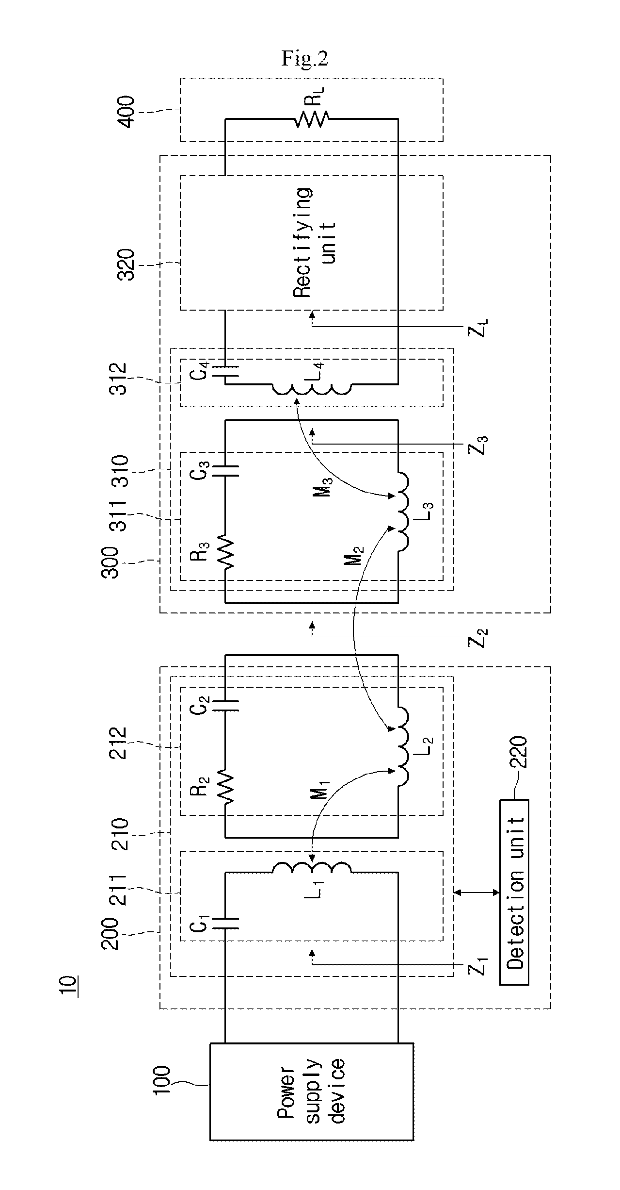
[0058]FIG. 2 is a circuit diagram showing the structure of the wireless power transmission system 10 according to the present invention.

[0059]In particular, FIG. 2 shows the structure of the wireless power transmission system 10 using the power supply device 100 having no power consumption preventing unit 150 described with reference to FIG. 1.

[0060]Referring to FIG. 2, the wireless power transmission system 10 according to the first embodiment of the present invention may include the power supply device 100, the wireless power transmitting apparatus 200, the wireless power receiving apparatus 300, and a load 400.

[0061]The power supply device 100 supplies AC power to the wireless power transmitting apparatus 200, and the wireless power transmitting apparatus 200 may transmit the supplied AC power to the wireless power receiving apparatus 300 through resonance.

[0062]The wireless power transmitting apparatus 200 may transmit power to the wireless power receiving apparatus 300 through ...

second embodiment

[0097]FIG. 5 is a circuit diagram showing the structure of the wireless power transmission system 20 according to the present invention.

[0098]Particularly, FIG. 5 is a circuit diagram showing the structure of the wireless power transmission system 20 using the power supply device 100 including the power consumption preventing unit 150.

[0099]Referring to FIG. 5, the wireless power transmission system 20 may include the power supply device 100, the wireless power transmitting apparatus 200, the wireless power receiving apparatus 300, and the load 400.

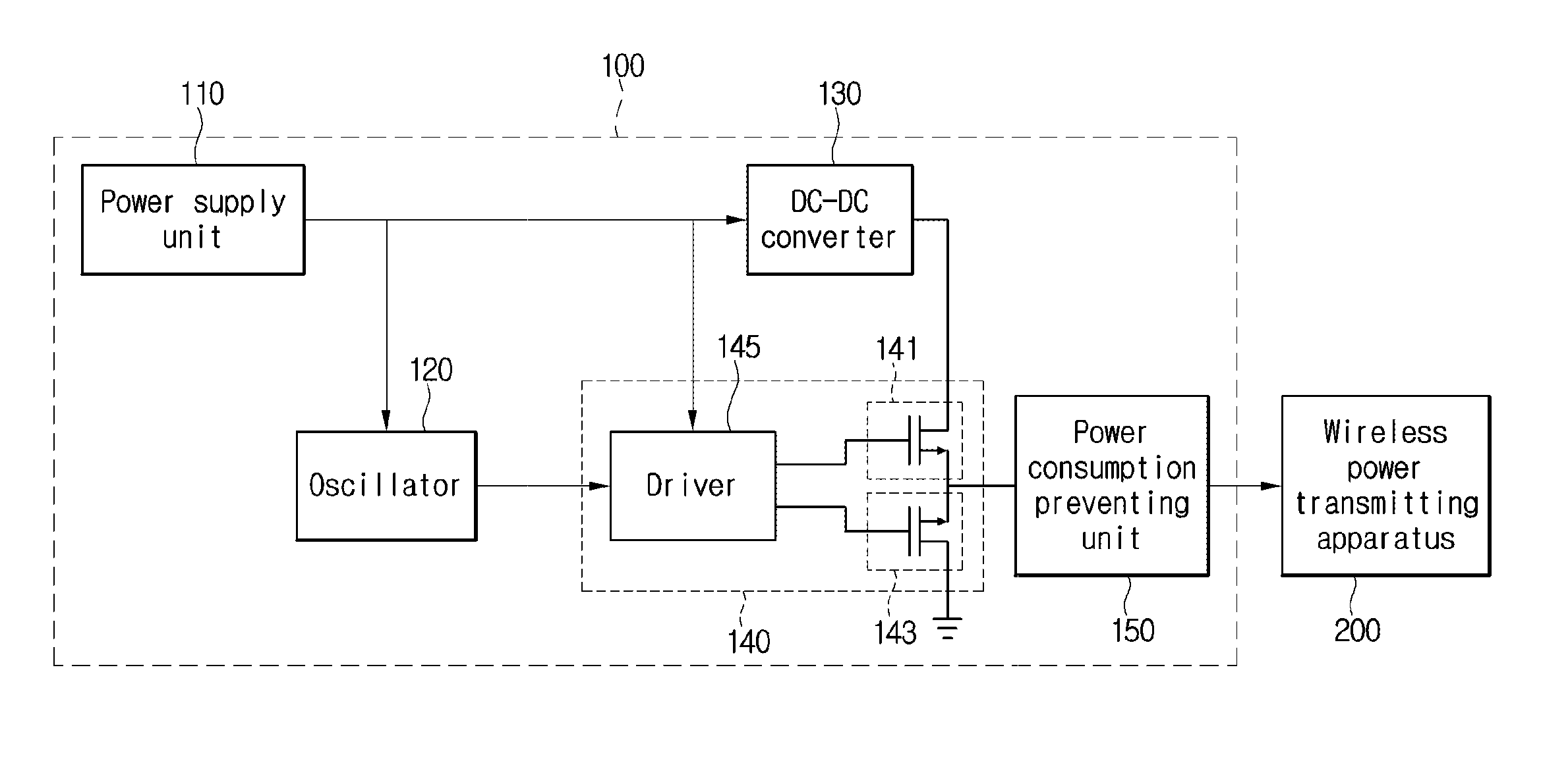
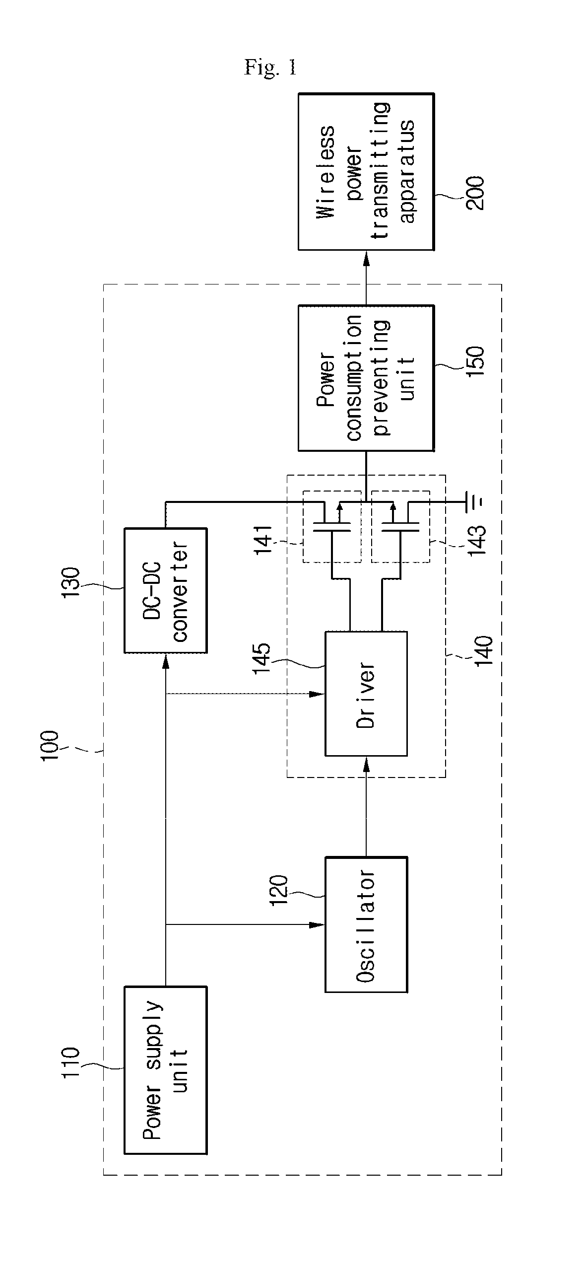
[0100]Although FIG. 5 shows that the power supply device 100 includes only both of the AC power generating unit 140 and the power consumption preventing unit 150, the description of the power supply device 100 may have the same components as those described with reference to FIG. 1.

[0101]In addition, the description of the wireless power transmitting apparatus 200, the wireless power receiving apparatus 300, and the load 400 is the same a...


PUM


Abstract

A power supply device for a wireless power transmitting apparatus according to an embodiment of the present invention includes a power supply unit to supply DC power, an AC power generating unit to generate AC power by using the DC power, and a harmonic component reduction unit to reduce a magnitude of power for a harmonic frequency component in the generated AC power.

Description

TECHNICAL FIELD[0001]The present invention relates to a wireless power transmitting technology. More particularly, the present invention relates to a wireless power transmitting technology, capable of maximizing power transmission efficiency through resonance or electromagnetic induction.BACKGROUND ART[0002]A wireless power transmission or a wireless energy transfer refers to a technology of wirelessly transferring electric energy to desired devices. In the 1800's, an electric motor or a transformer employing the principle of electromagnetic induction has been extensively used and then a method for transmitting electrical energy by irradiating electromagnetic waves, such as radio waves or lasers, has been attempted. Some electric toothbrushes or wireless razors, which are usually used, are actually charged with electricity through an electromagnetic induction principle. The electromagnetic induction refers to a phenomenon in which a voltage is induced so that a current flows when a ...

Claims


Application Information

Patent Timeline
IPC IPC(8): H02J17/00H02J3/01
CPCH02J17/00H02J3/01H02J50/12H02J50/10
Inventor BAE, SU HO
Owner SCRAMOGE TECH LTD
Why Eureka
Try Eureka