Split-pressure dual pump hydraulic fluid supply system for a multi-speed transmission and method

a dual-pump, hydraulic fluid technology, applied in the direction of machines/engines, liquid fuel engines, positive displacement liquid engines, etc., can solve the problems of high oil pressure, not only inefficient, and affecting the reliability and durability of the transmission

Active Publication Date: 2012-03-06
GM GLOBAL TECH OPERATIONS LLC
View PDF14 Cites 10 Cited by
  • Summary
  • Abstract
  • Description
  • Claims
  • Application Information

AI Technical Summary

Benefits of technology

[0012]In a preferred embodiment, the first pump is a fixed displacement (“PF”) pump and the second pump is a variable displacement (“PV”) pump. However, it is also considered to be within the scope of the present invention that both pumps be PV pumps. It is preferred that the high-pressure work circuit is not fluidly coupled to the first pump, and the low-pressure work circuit is not fluidly coupled to the second pump. In this preferred embodiment, the invention separates the low-flow, high-pressure needs of the transmission into a separate work circuit from the high-flow, low-pressure needs, and optimizes pump design separately for each circuit portion to maximize transmission efficiency. The combination of a PF pump and PV pump in a regulated system has the advantage of the instant acting fluid delivery inherent in a fixed displacement pump, and the high pressure, low horsepower consuming characteristics available with a variable displacement pump. A combination pump system therefore maximizes performance, efficiency, and dependability while minimizing costs.
[0015]The oil pump assembly also includes a third conduit which defines a decrease circuit that is fluidly coupled to the regulator and the PV pump for reducing the flow of fluid to the high-pressure work circuit. It is preferred that there is no fluid coupling between the decrease circuit and either the PF pump or the reservoir. The oil pump assembly preferably also includes a fourth conduit that defines an overage circuit. The overage circuit is fluidly coupled to the regulator and the PV pump, but is not fluidly coupled to the PF pump. The overage circuit is a “backup” feature for further reducing the flow of fluid to the high-pressure work circuit when the decrease circuit is at full capacity and the PV pump is still pumping more fluid then demanded by the high-pressure work circuit.

Problems solved by technology

It is well known that the lubricating and cooling capabilities of transmission oil systems greatly impact the reliability and durability of the transmission.
First, high oil pressure has traditionally been required to maintain torque converter charge pressure, which is the torque converter oil inlet pressure at the centerline of the transmission.
It is necessary to maintain this pressure to avoid cavitation, which is not only inefficient, but can be damaging to the internal componentry of the torque converter.
The single PF system is inefficient in applications requiring high-pressure fluid because the PF pump continues to deliver high flow, high pressure fluid even when only low pressure and / or low flow is needed.
This parasitic loss results in unnecessary consumption of power from the motor vehicle engine or battery and may tend to reduce the overall life of the pump.
In systems where the hydraulic circuit has a relief valve, the valve will “dump” excess fluid flow as it is being pumped by the PF pump, thereby generating undesirable heat in the hydraulic fluid.
However, PF systems with multiple pumps still have the high pressure deficiencies mentioned above.

Method used


Image

  • Split-pressure dual pump hydraulic fluid supply system for a multi-speed transmission and method
  • Split-pressure dual pump hydraulic fluid supply system for a multi-speed transmission and method
  • Split-pressure dual pump hydraulic fluid supply system for a multi-speed transmission and method

Examples


Embodiment Construction

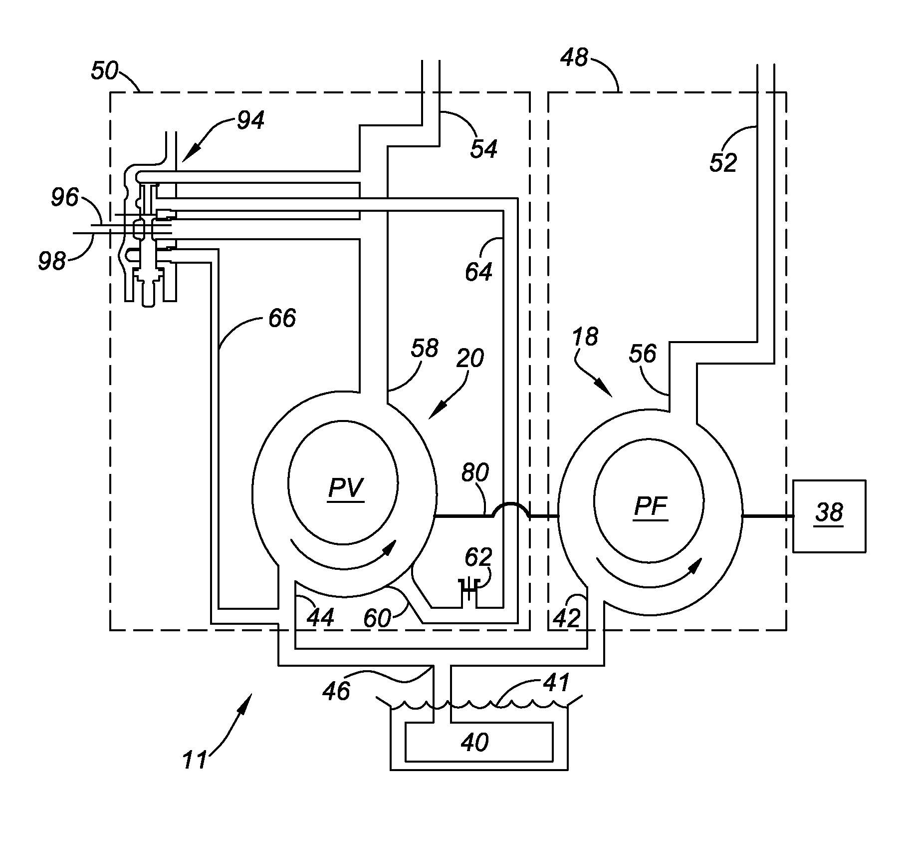
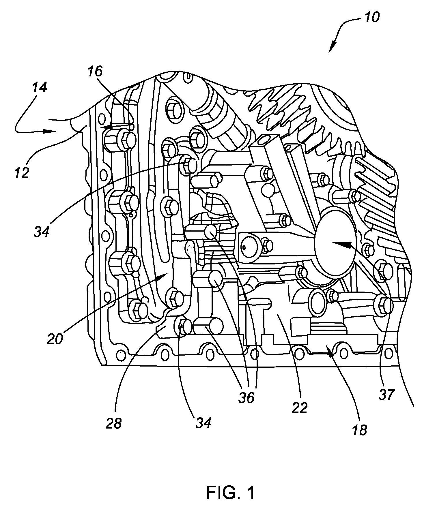
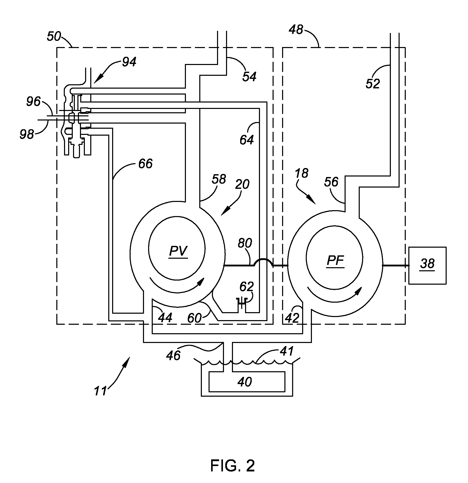
[0022]Referring to the drawings, wherein like reference numbers refer to like components throughout the several views, FIG. 1 illustrates an oil pump assembly or oil pump system, shown generally as 10, in accordance with the present invention. The oil pump assembly 10, described herein for supplying hydraulic fluid to a multi-speed power transmission (not shown) of an automobile (not shown), may also be applied in other various applications, such as, by way of example, aeronautical vehicles (e.g., airplanes, helicopters, etc.), agricultural vehicles (e.g., combine, tractor, etc.), construction vehicles (e.g., forklift, backhoe, excavator, etc.), and stationary machines (e.g., hydraulic press, hydraulic drill, etc.).

[0023]The oil pump assembly 10 includes an assembly housing 12 having opposing front and rear faces 14, 16 (FIG. 1), respectively, and a first pump 18 in face-to-face relation with a second pump 20. The first pump 18 (illustrated in an exemplary embodiment in FIG. 4) is p...


PUM


Abstract

A split-pressure, dual-pump system for supplying hydraulic fluid to a multi-speed transmission is provided. The system includes a low-pressure work circuit operatively connected to a fixed displacement pump, and a high-pressure work circuit operatively connected to a variable displacement pump. The system also includes a regulator valve fluidly coupled to the variable displacement pump via a decrease circuit and an overage circuit for regulating the flow of fluid to the high-pressure work circuit. The invention consists of separating the high-pressure needs of the system into a separate work circuit from the low-pressure needs of the system, and optimizing pump design separately for each work circuit to maximize transmission efficiency and reduce parasitic losses. A method of supplying hydraulic fluid to a multi-speed transmission at variable flow and pressure is also provided.

Description

TECHNICAL FIELD[0001]The present invention relates to hydraulic fluid control systems, namely oil supply systems for multi-speed transmissions having dual pumps working in unison and controlled by a regulating valve.BACKGROUND OF THE INVENTION[0002]Automotive and commercial vehicles include a powertrain that is comprised of an engine, a multi-speed transmission, and a differential or final drive. The multi-speed power transmission requires a supply of pressurized fluid to properly operate. The pressurized fluid may be used for such functions as cooling, lubrication, and torque converter operation. It is well known that the lubricating and cooling capabilities of transmission oil systems greatly impact the reliability and durability of the transmission. Additionally, multi-speed power transmissions require the hydraulic system to provide controlled engagement and disengagement, on a desired schedule, of the various torque transmitting mechanisms that operate to establish the speed ra...

Claims


Application Information

Patent Timeline
Patent Type & Authority Patents(United States)
IPC IPC(8): F04B49/00F16H57/04
CPCF04C2/102F04C2/3442F04C11/005F04C14/226F16H57/04
Inventor EARHART, DAVID E.RODGERS, II, DANE L.
Owner GM GLOBAL TECH OPERATIONS LLC
Why Eureka
Try Eureka