
Over Device of Tunnel-Type Sterilization Dryer

a dryer and tunnel-type technology, applied in drying machines, drying machines with progressive movements, lighting and heating apparatus, etc., can solve the problems of direct impact on the functionality of the device, inability to effectively control the temperature of the entire heating surface in the heating chamber, and common overheating, etc., to achieve superior hot air uniformity, simple and compact size, and low cost

Active Publication Date: 2012-08-30
TRUKING TECH LTD
View PDF26 Cites 10 Cited by
  • Summary
  • Abstract
  • Description
  • Claims
  • Application Information

AI Technical Summary

Benefits of technology

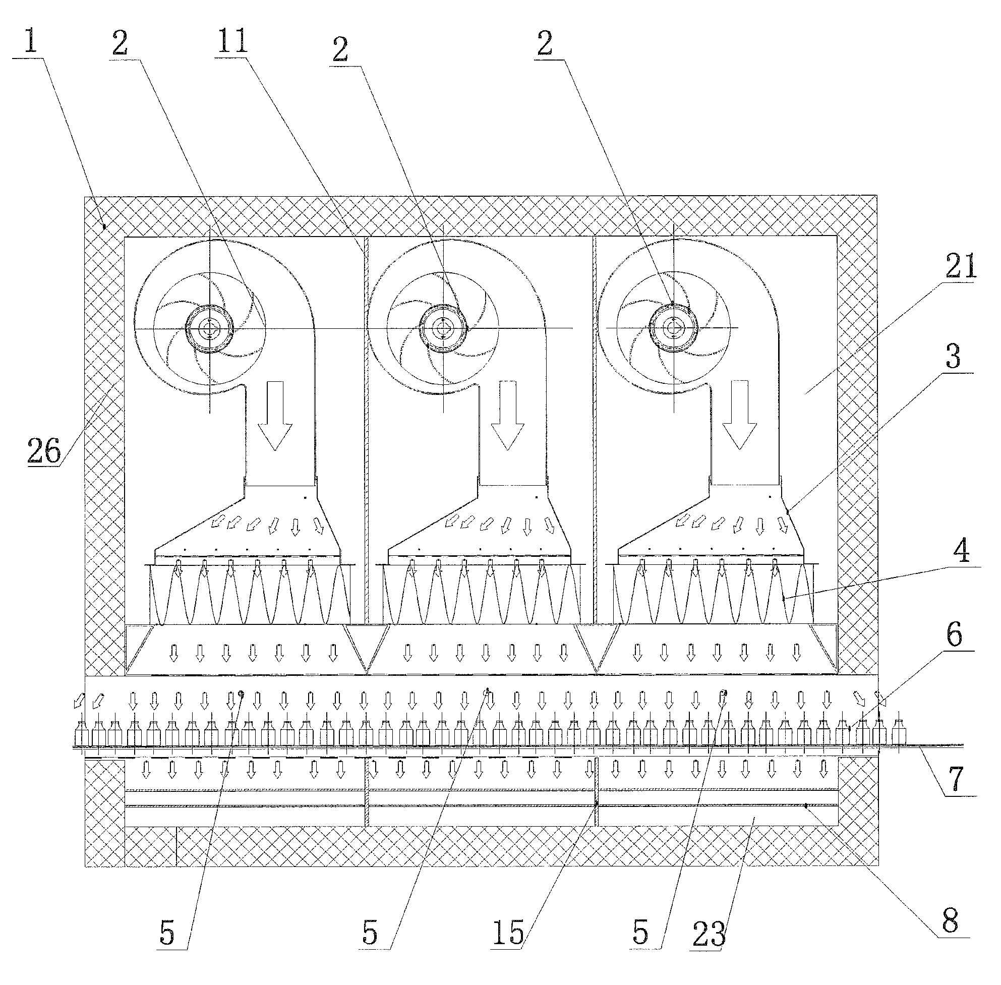
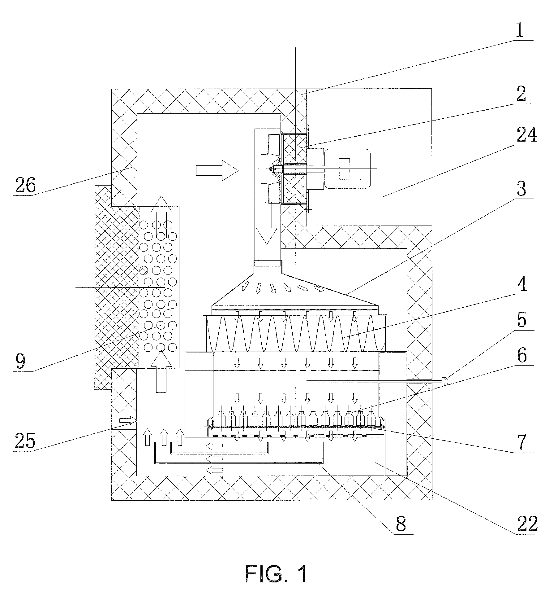
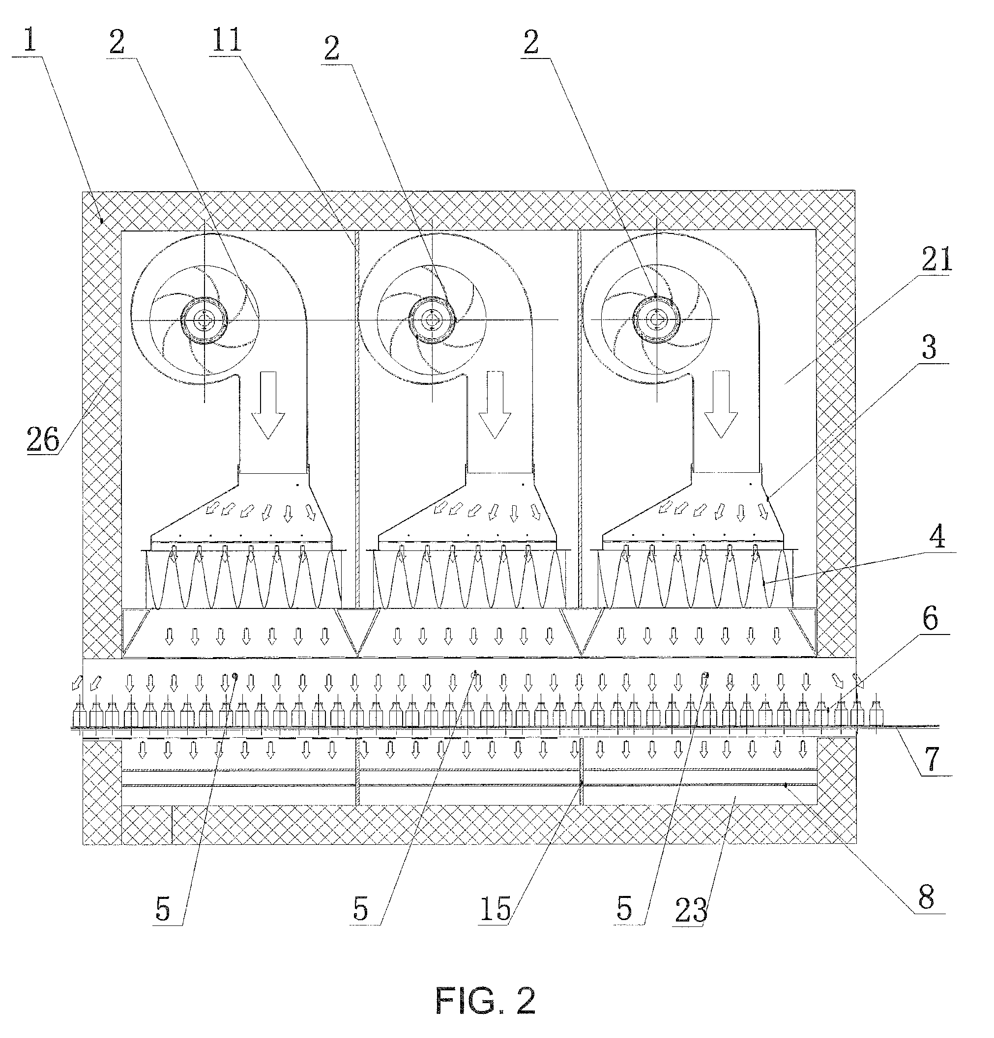
The present invention is a tunnel-type sterilizer and dryer oven device that is simple and compact in size, low in cost, suitable for applications in different areas, and superior in uniformity of hot air. The device includes an air intake cavity with one or more air intake partition boards that divide the cavity into independent air intake chambers with heaters and hot air generators, diffuser fan covers, high efficiency filters, and temperature probes. The device also has an air return channel with one or more air return chamber partition boards that divide the channel into air return passages with exit ends at the bottom of the heater. The case body has a supplemental air inlet and the interior surface has a heat retaining layer. The invention provides better temperature control and uniformity of hot air for use in a variety of production lines.

Problems solved by technology

Accordingly, the provision of only one point in the middle of the heating chamber fails to effectively control the temperature of the entire heating surface in the heating chamber.
Therefore, problem of over-heat is common for the conventional oven.
Also, temperature difference between a front and a back portion of the heating chamber not only affects the uniformity of temperature, but also has a direct impact on the functionality of the device.
When the temperature is too high, parts of the heating chamber may be damaged (for example, the high temperature high efficiency filter usually has a maximum temperature threshold of operation).

Method used


Image

  • Over Device of Tunnel-Type Sterilization Dryer
  • Over Device of Tunnel-Type Sterilization Dryer
  • Over Device of Tunnel-Type Sterilization Dryer

Examples


Embodiment Construction

[0019]The tunnel-type sterilizer and dryer oven device is further described with the accompanying drawings and illustrative examples as follows.

[0020]Referring to FIG. 1, FIG. 2 and FIG. 3 of the drawings, a tunnel-type sterilizer and dryer oven device according to a preferred embodiment of the present invention includes a case body 1, an air intake cavity 24, a conveyor belt 7 and an air return channel 22 provided in the case body 1. The conveyor belt 7 is positioned between the air return channel 22 and the air intake cavity 24. The oven device comprises one or more air intake partition boards 11 in the air intake cavity 24 to divide the air intake cavity 24 into two or more independent air intake chambers 21, wherein each the air intake chamber 21 comprises a heater 9, and a hot air generator 2, a diffuser fan cover 3, a high temperature high efficiency filter 4 and a temperature probe 5 sequentially provided from a top portion to a bottom portion of the air intake chamber 21, wh...


PUM


Abstract

An baking case body of tunnel type sterilization dryer comprises a case body (1), an air intake cavity (24) which is disposed in the case body (1), a conveyor mesh belt (7), and an air return channel (22). The conveyor mesh belt (7) is located between the air return channel (22) and the air intake cavity (24). The air intake cavity (24) is divided into two or more than two independent air intake chambers (21) by one or more than one air intake partition boards (11). A heater (9) is disposed in each air intake chamber (21), and a hot air generator (2), a diffuser fan cover (3), a high temperature and high efficient filter (4) and a temperature probe (5) are disposed sequentially in each air intake chamber (21) from top to bottom. Air return partition boards (15) are arranged in the air return channel (22), corresponding to the air intake partition boards (11). The air return channel (22) is divided into two or more than two air return cavities (23) by the air return partition boards (15). The exit end of the air return cavity (23) is located at the bottom of the heater (9). The structure of the baking case body of tunnel type sterilization dryer is simple and compact, and the uniformity of the hot air is good.

Description

BACKGROUND OF THE PRESENT INVENTION[0001]1. Field of Invention[0002]The present invention relates to a machinery for packaging which is used in food and pharmaceutical industries, and more particularly to a sterilizer and dryer device for food and pharmaceutical industries.[0003]2. Description of Related Arts[0004]In food and pharmaceutical packaging machinery industries, uniformity of heat to flow is an important index for research in sterilizer and dryer device which utilizes circulating hot air. The heating principle is carrying out heat exchange through a heater and a circulating air flow. The circulating air is first heated by the heater, guided to flow into a wind shield and to a high temperature high efficiency filter device, and then having heat exchange with food or pharmaceutical bottle. Generally, the control method includes one temperature probe positioned in the middle of a heating chamber of the oven which is used as the point of control to detect the temperature of ai...

Claims


Application Information

Patent Timeline
Patent Type & Authority Applications(United States)
IPC IPC(8): F26B15/18F26B21/02F26B25/06
CPCF26B21/02F26B15/18
Inventor CAI, DAYUNING, ZHIGAOYI, BOZHU, ZANMINGLIU, ZHENTANG, YUE
Owner TRUKING TECH LTD
Learn More