Transmission for tractor

a technology for tractors and transmissions, applied in mechanical devices, transportation and packaging, gearing, etc., can solve the problems of excessive lengthening of transmissions, increasing the minimum turning radius, and increasing engine power consumption, so as to simplify the structure of transmissions and facilitate the transmission. the effect of manipulation

Inactive Publication Date: 2011-01-25
LS MTRON LTD
View PDF5 Cites 0 Cited by
  • Summary
  • Abstract
  • Description
  • Claims
  • Application Information

AI Technical Summary

Benefits of technology

[0009]Accordingly, the present invention has been made to solve the above-mentioned problems occurring in the prior art, and an object of the present invention is to provide a transmission for a tractor in which a high speed / low speed transmission part and a forward / reverse transmission part are integrated with each other so that the whole length is shortened, and a transmission shaft of the forward / reverse transmission part is also utilized as a driving shaft for high speed / low speed transmission, thereby making the structure thereof simple and compact in size.
[0012]The clutches may be a hydraulic multiple disk clutch. According to this, the clutches can be driven with hydraulic force, so that the manipulation of the transmission becomes convenient as compared to the case where a device such as a synchronizer and a link-associated clutch are used, and a transmission lever is forced to operate manually, and that the structure of the transmission is simplified due to removal of a complicated link mechanism.

Problems solved by technology

In such a transmission, although the power shift type by the hydraulic clutches is introduced for convenience of transmission, all gears from the forward / reverse transmission part to the super low speed transmission part are arranged longitudinally in a single row, i.e., in forward and reverse directions, so that a problem is caused in that a length of the transmission is lengthened excessively.
For example, as the length of the transmission is lengthened, a distance between a front wheel and a rear wheel becomes far away to problematically increase a minimum turning radius as well as power consumption of the engine due to increased weight of the transmission.

Method used


Image

  • Transmission for tractor
  • Transmission for tractor
  • Transmission for tractor

Examples


Embodiment Construction

[0021]Hereinafter, exemplary embodiments of the present invention will be described in detail with reference to the accompanying drawings.

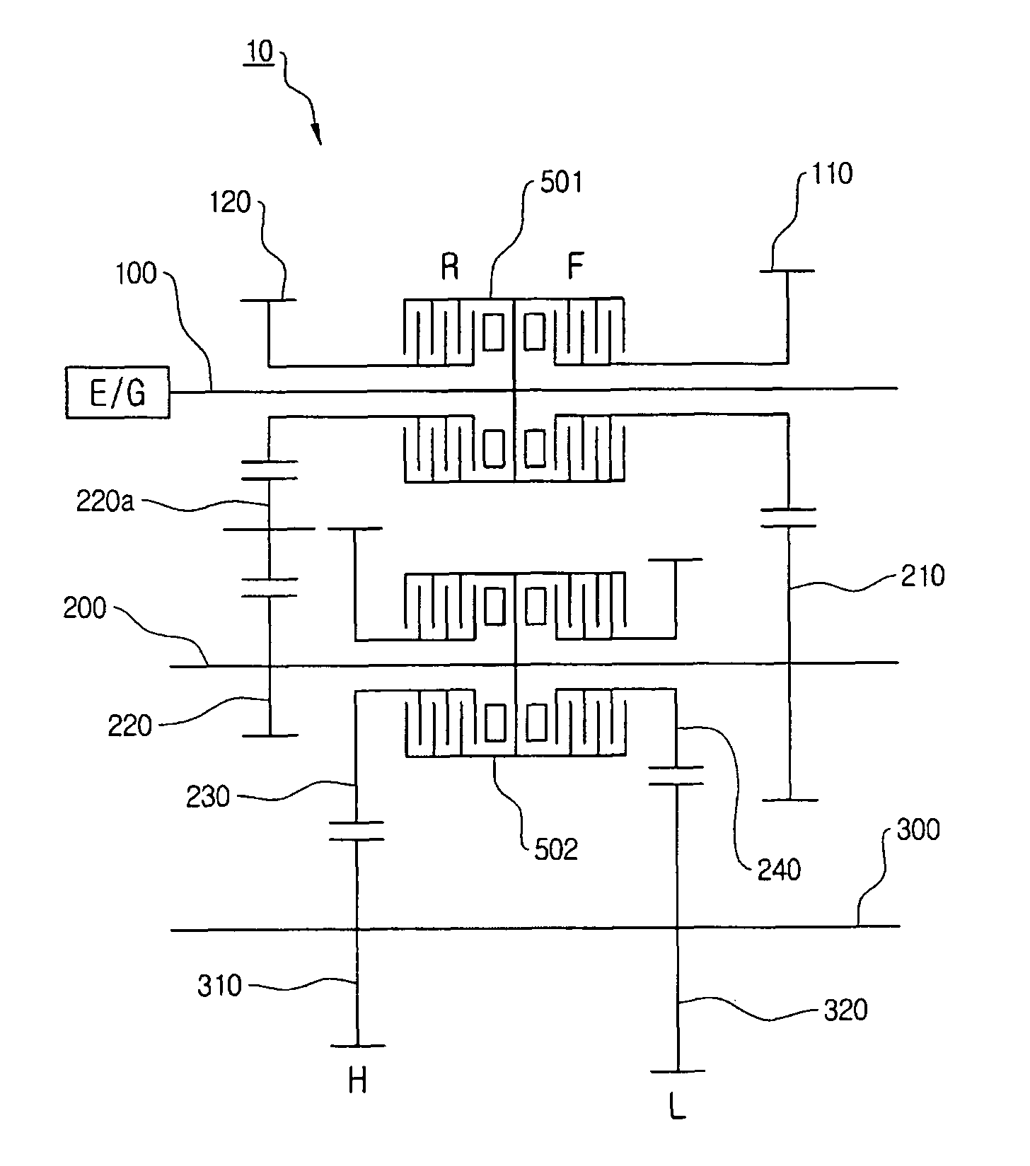
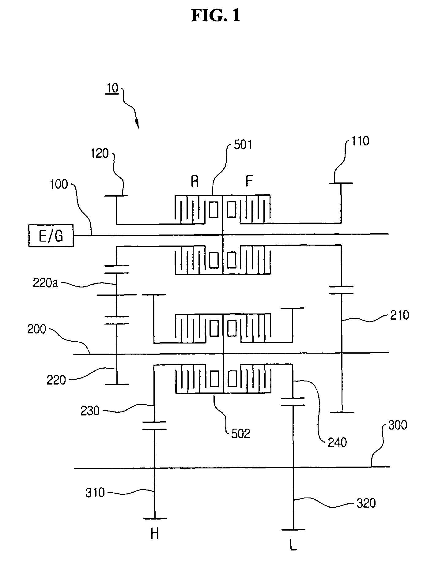
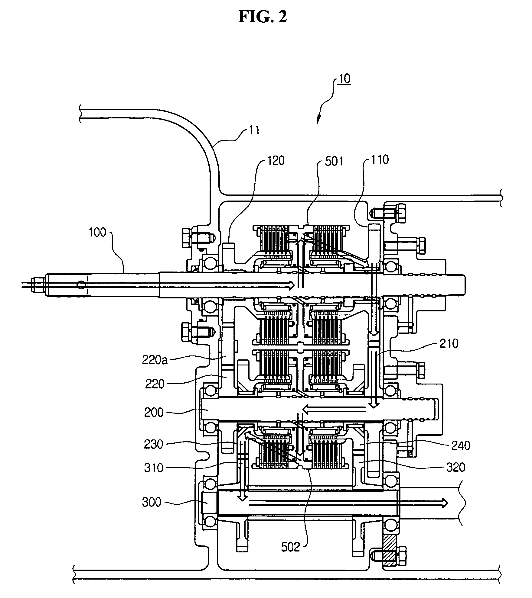
[0022]As shown in FIG. 1, the transmission includes an input shaft 100, an idle shaft 200, and an output shaft 300, which are arranged parallel with each other, such that a forward / reverse transmission part and a high speed / low speed transmission part are disposed in one region of a transmission case. The input shaft 100 serves to receive power from an engine, and the idle shaft 200 serves to mediate the forward / reverse movement and functions as a driving shaft for high speed / low speed transmission. The output shaft 300 receives the power from the idle shaft 200 and transmits it to the main transmission part (not shown).

[0023]A forward driving gear 110 and a reverse driving gear 120 are installed on the input shaft 100 such that they are able to rotate idle on the input shaft 100 through support by a bearing. A forward / reverse clutch 501 is instal...


PUM


Abstract

A transmission for a tractor has an input shaft receiving power from an engine, an idle shaft disposed parallel with the input shaft, an output shaft disposed parallel with the idle shaft and transmitting power to a main transmission part, forward / reverse driving gears installed on the input shaft so as to rotate idle, a forward / reverse clutch installed between the forward driving gear and the reverse driving gear to selectively connect the forward driving gear or the reverse driving gear to the input shaft, a forward driven gear installed on the idle shaft and engaged with the forward driving gear, a reverse driven gear installed on the idle shaft and engaged with the reverse driving gear, high speed / low speed driving gears installed between the forward driven gear and the reverse driven gear so as to rotate idle, a high speed / low speed clutch installed between the high speed driving gear and the low speed driving gear to selectively connect the high speed driving gear or the low speed driving gear to the idle shaft, and high speed / low speed driven gears installed on the output shaft and engaged with the high speed driving gear and the low speed driving gear, respectively.

Description

CROSS-REFERENCE TO RELATED APPLICATION[0001]This application claims all benefits of Korean Patent Application No. 10-2007-0048066 filed on May 17, 2007 in the Korean Intellectual Property Office, the disclosures of which are incorporated herein by reference.BACKGROUND OF THE INVENTION[0002]1. Field of the Invention[0003]The present invention relates to a transmission for a tractor, and more particularly to a transmission for a tractor in which a high speed / low speed transmission part and a forward / reverse transmission part are integrated with each other, making the structure thereof simple and compact.[0004]2. Description of the Prior Art[0005]Generally, a transmission for a tractor is formed in type of a series of transmission parts that are connected in order from an engine. That is, the transmission generally includes a forward / reverse transmission part that changes a direction of rotating power of the engine to a forward / reverse direction, a main transmission part that changes s...

Claims


Application Information

Patent Timeline
Patent Type & Authority Patents(United States)
IPC IPC(8): F16H3/093
CPCF16H37/043F16H2003/0936F16H2037/044F16H2037/045Y10T74/19233F16H2200/003F16H2200/0034F16H2200/0086Y10T74/19223F16H2037/049B60K17/06
Inventor KIM, HYO-JUNGKIM, HYUNG-TAILEE, SANG-HEON
Owner LS MTRON LTD
Why Eureka
Try Eureka