

Lens driving device, camera module mounted with the lens driving device, and mobile telephone mounted with the camera module
- Summary
- Abstract
- Description
- Claims
- Application Information
AI Technical Summary
Benefits of technology
Problems solved by technology
Method used
Image

Examples
first exemplary embodiment
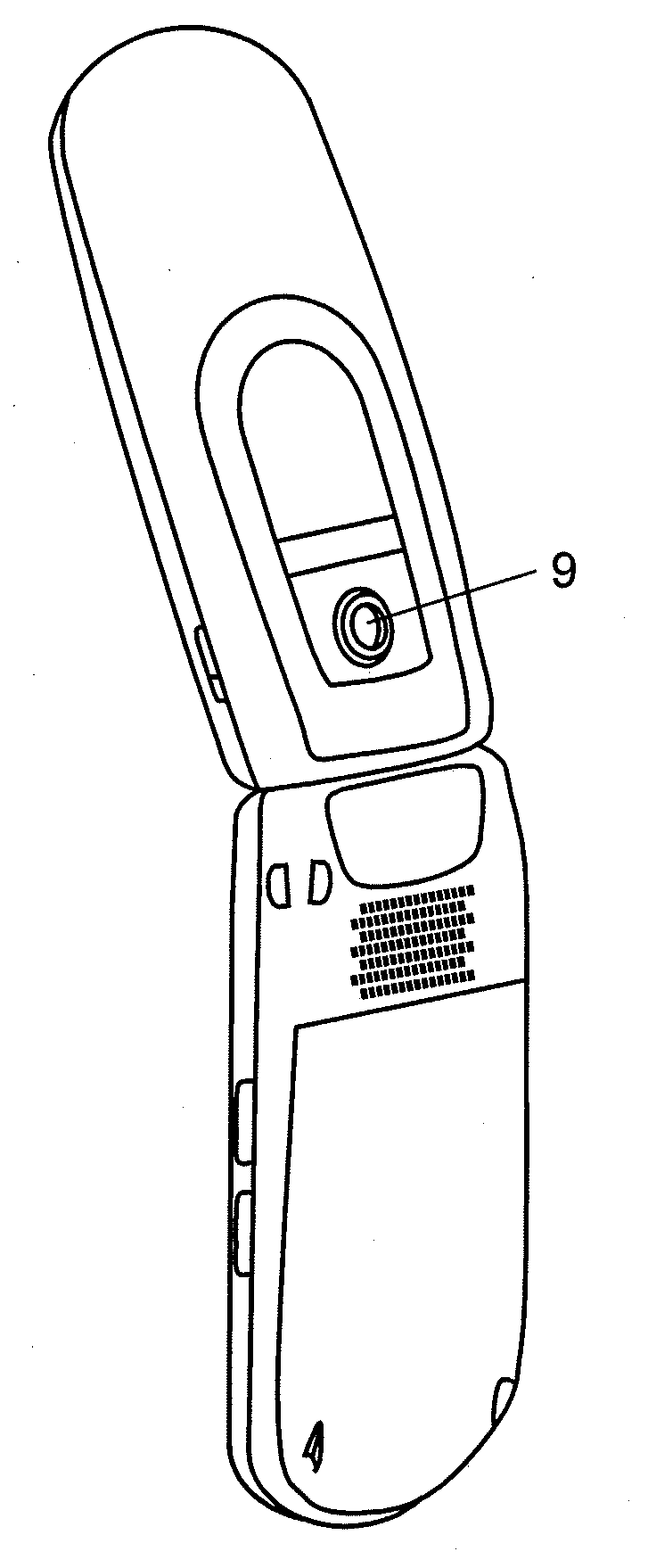
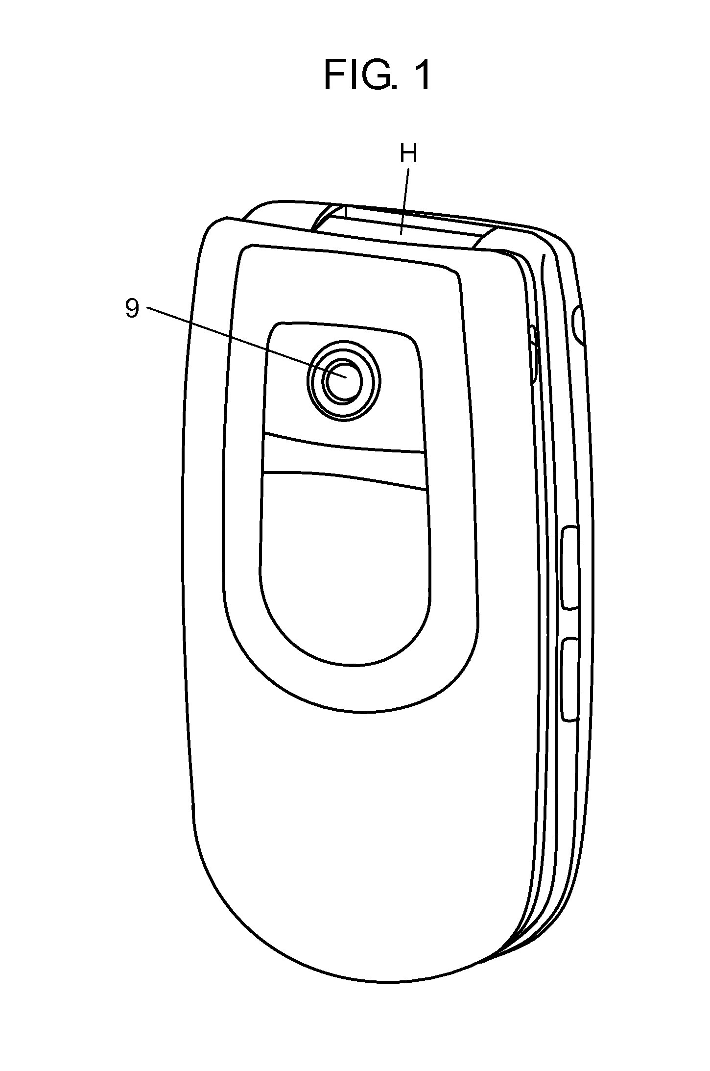
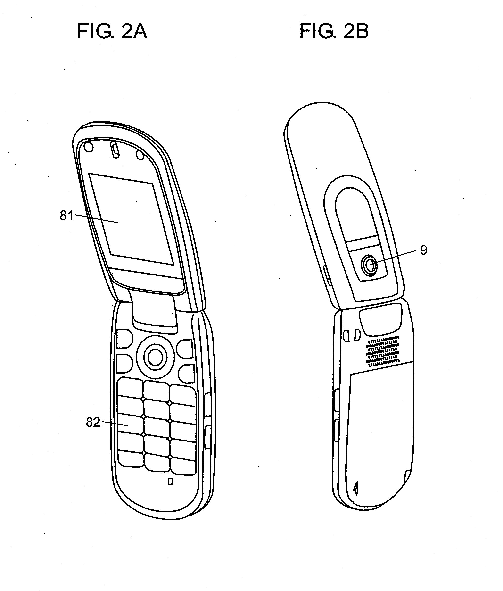
[0038]Hereinafter, a description is made of an embodiment of a mobile telephone of the present invention using the related drawings. As shown in FIG. 1, the mobile telephone is foldable centering on hinge H. FIG. 1 shows a folded state, where cover glass 9, a part of the camera module, is exposed on the front. FIG. 2A shows a state where the mobile telephone is unfolded with display unit 81 and operation unit 82 on the front. FIG. 2B shows the mobile telephone unfolded viewed from the back. The user points cover glass 9 at an object with the telephone unfolded, and while viewing the image on display unit 81, the user operates operation unit 82 to release the shutter for photographing the object.
[0039]Next, a description is made of a configuration of the camera module in a case where lens driving device 1 of the embodiment is incorporated into a camera, in reference to FIG. 3.
[0040]As shown in FIG. 3, lens driving device 1 has filter 2 and image sensor 3 disposed at the side of base ...
second exemplary embodiment
[0063]Next, a description is made of a mobile telephone according to the second embodiment of the present invention referring to FIG. 7. The second embodiment is structured so that only the structure of holder 10, especially main shaft guide unit 15, of the first embodiment is changed, and thus detailed description is omitted for the same part.
[0064]In the second embodiment, as shown in FIG. 7, main shaft guide unit 15 is formed as a through hole extended in the direction of the optical axis, of holder 10 instead of a groove extended in the direction of the optical axis, of holder 10. Even in this case, the cross-section shape of the surface vertical to the optical axis, of main shaft guide unit 15 includes a V shape, and the vertex of the V shape projects in the direction opposite to that of force ½ F in the direction vertical to the optical axis. Accordingly, similarly to the first embodiment, main shaft guide unit 15 is pressed against main shaft 51 with a force of the same direc...
third exemplary embodiment
[0066]Next, a description is made of a mobile telephone according to the third embodiment of the present invention referring to FIG. 8. The third embodiment is structured so that only the structure of holder 10, especially main shaft guide unit 15, of the first and second embodiments has been changed, and thus detailed description is omitted for the same part.
[0067]In the third embodiment as well, as shown in FIG. 8, main shaft guide unit 15 is formed as a through hole extended in the direction of the optical axis, of holder 10. The cross section of the surface vertical to the optical axis, of main shaft guide unit 15 has three sliding contact sections 15a, 15b, and 15c formed as a result that the inner circumferential surface of the through hole projects toward the central axial direction of the through hole. Resultingly, even if force ½ F (shown in the figure) in the direction vertical to the optical axis is not present, sliding contact sections 15a, 15b, and 15c continue to slidi...
PUM
 Abstract
Description
Claims
Application Information