Cutting structures for fixed cutter drill bit and other downhole cutting tools

a technology of drilling structure and drill bit, which is applied in the direction of drill bits, earthwork drilling and mining, construction, etc., can solve the problems of loss of penetration rate, premature wear or destruction of cutting elements, and process known as drill string stripping

Active Publication Date: 2012-09-20
SMITH INT INC
View PDF5 Cites 49 Cited by
  • Summary
  • Abstract
  • Description
  • Claims
  • Application Information

AI Technical Summary

Benefits of technology

[0024]Other aspects and advantages of the invention will be apparent from the following description and the appended claims.

Problems solved by technology

This process, known as a “trip” of the drill string, requires considerable time, effort, and expense.
Such whirling subjects the cutting elements on the bit to increased loading, which causes premature wearing or destruction of the cutting elements and a loss of penetration rate.
Thus, preventing bit vibration and maintaining stability of PDC bits has long been a desirable goal, but one which has not always been achieved.
Bit vibration typically may occur in any type of formation, but is most detrimental in the harder formations.
However, as PDC bits are being developed for use in harder formations, bit stability is becoming an increasing challenge.
As previously described, excessive bit vibration during drilling tends to dull the bit and / or may damage the bit to an extent that a premature trip of the drill string becomes necessary.
Unfortunately, may of the bit designs aimed at minimizing vibration require that drilling be conducted with an increased weight-on-bit (WOB) as compared to bits of earlier designs.
This additional weight increases the stress and strain on all drill string components, causes stabilizers to wear more and to work less efficiently and increases the hydraulic drop in the drill string, requiring the use of higher capacity (and typically higher cost) pumps for circulating the drilling fluid.
Compounding the problem still further, the increased WOB causes the bit to wear and become dull much more quickly than would otherwise occur.
The relationship between bit wear and WIB is not linear, but is an exponential one, such that upon exceeding a particular WOB for a given bit, a very small increase in WOB will cause a tremendous increase in bit wear.
Thus, adding more WOB so as to drill with a partially worn bit further escalates the wear on the bit and other drill string components.

Method used


Image

  • Cutting structures for fixed cutter drill bit and other downhole cutting tools
  • Cutting structures for fixed cutter drill bit and other downhole cutting tools
  • Cutting structures for fixed cutter drill bit and other downhole cutting tools

Examples


Embodiment Construction

[0067]In one aspect, embodiments disclosed herein relate to fixed cutting drill bits or other downhole cutting tools containing multiple types of cutting structures. In particular, embodiments disclosed herein relate to drill bits containing two or more types of cutting elements, each type having a different mode of cutting action against a formation. Other embodiments disclosed herein relate to fixed cutter drill bits containing conical cutting elements, including the placement of such cutting elements on a bit and variations on the cutting elements that may be used to optimize drilling.

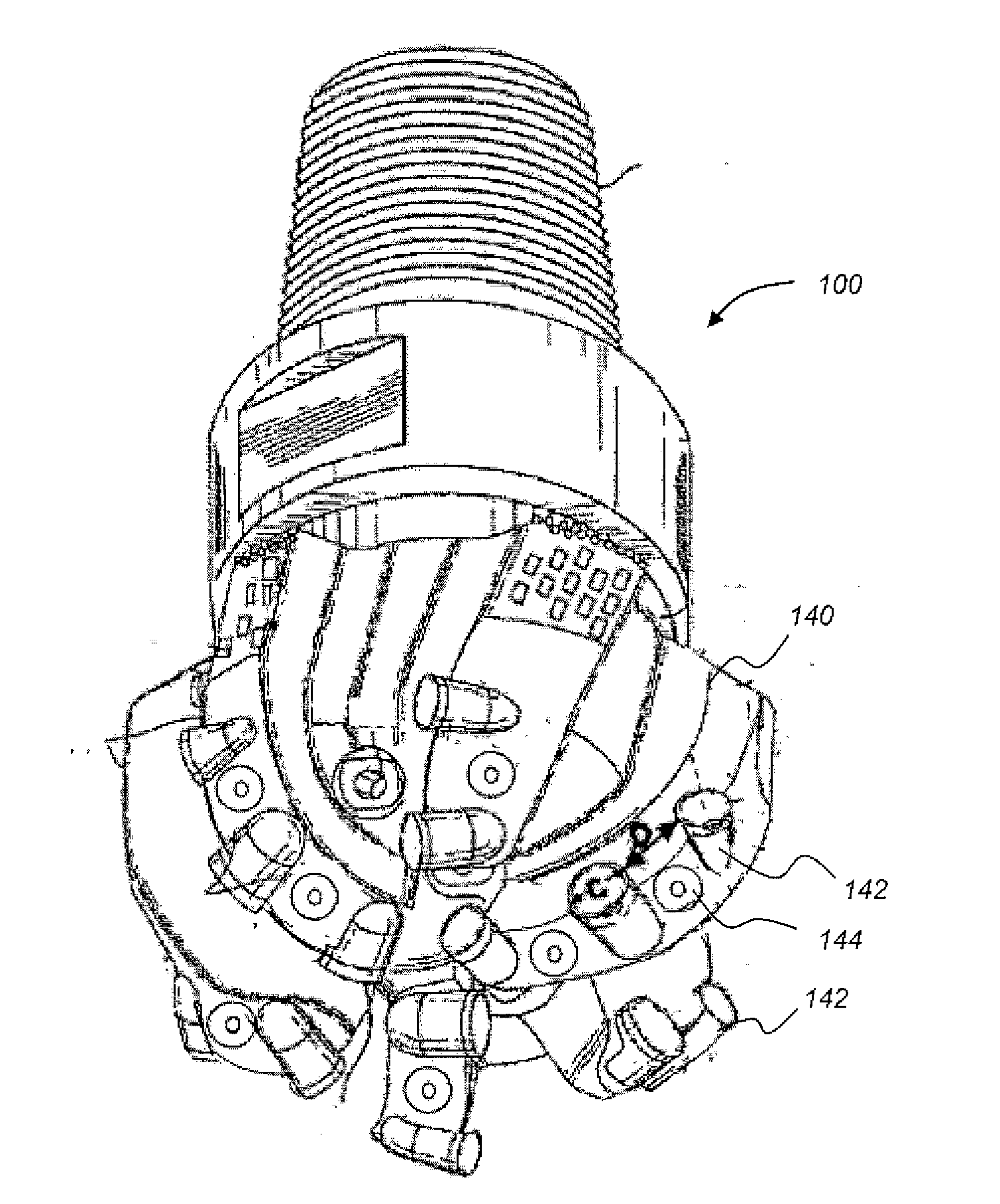
[0068]Referring to FIGS. 4 and 5, representative blades having cutting elements thereon for a drill bit (or reamer) formed in accordance with one embodiment of the present disclosure are shown. As shown in FIG. 4, the blade 140 includes a plurality of cutters 142 conventionally referred to as cutters or PDC cutters as well as a plurality of conical cutting elements 144. As used herein, the term “con...


PUM


Abstract

A downhole cutting tool may include a tool body; a plurality of blades extending azimuthally from the tool body; and a plurality of cutting elements disposed on the plurality of blades, the plurality of cutting elements comprising: at least two conical cutting elements comprising a substrate and a diamond layer having a conical cutting end, wherein at least one of the at least two conical cutting elements has a positive back rake angle, and at least one of the at least two conical cutting elements has a negative back rake angle.

Description

CROSS-REFERENCE TO RELATED APPLICATIONS[0001]This application claims priority to U.S. Application No. 61 / 441,319, filed on Feb. 10, 2011, and U.S. Patent Application No. 61 / 499,851, filed on Jun. 22, 2011, both of which are herein incorporated by reference in their entirety.BACKGROUND[0002]1. Field[0003]Embodiments disclosed herein generally relate to fixed cutter cutting tools containing cutting structures containing two or more types of cutting elements, each type having a different mode of cutting action against a formation. Other embodiments disclosed herein relate to fixed cutter cutting tools containing conical cutting elements, including the placement of such cutting elements on a bit and variations on the cutting elements that may be used to optimize drilling.[0004]2. Background Art[0005]In drilling a borehole in the earth, such as for the recovery of hydrocarbons or for other applications, it is conventional practice to connect a drill bit on the lower end of an assembly of...

Claims


Application Information

Patent Timeline
Patent Type & Authority Applications(United States)
IPC IPC(8): E21B10/46
CPCE21B10/26E21B10/55E21B10/62E21B10/567E21B10/5673E21B10/43E21B10/58E21B10/46E21B10/54E21B10/56E21B10/485E21B10/633E21B10/627
Inventor AZAR, MICHAEL G.DURAIRAJAN, BALAKESHAVAN, MADAPUSI K.
Owner SMITH INT INC
Why Eureka
Try Eureka