Dummy plug

a dummy plug and plug-in technology, applied in the direction of coupling device connection, coupling base/case, securing/insulating coupling contact member, etc., can solve the problem of weak engagement force of retaining portion and resilient locking piece, difficult to ensure a sufficiently large deformation margin, etc. problem, to achieve the effect of simplifying the shape of the dummy plug

Inactive Publication Date: 2012-09-20
SUMITOMO WIRING SYST LTD
View PDF6 Cites 2 Cited by
  • Summary
  • Abstract
  • Description
  • Claims
  • Application Information

AI Technical Summary

Benefits of technology

[0010]The resilient locking pieces engage the retaining portions to hold the dummy plug in the retained state in the connector. The resilient locking pieces are supported on both front and rear ends by the sealing portion and the support. Thus, deformation rigidity is high and engaging forces of the resilient locking pieces and the retaining portions are strong as compared with resilient locking pieces supported on one end. In addition, the two resilient locking pieces share the deformation space. Thus, only the deformation space is present between the resilient locking pieces. Accordingly, a sufficiently large warping margin is ensured for the resilient locking pieces. The reliability of a retaining function is improved because the engaging forces of the resilient locking pieces and the retaining portions are increased and a sufficient engagement margin is ensured for the resilient locking pieces and the retaining portions as just described.
[0012]The part of the operating portion used to mount and remove the dummy plug into and from the connector functions as the support for supporting the resilient locking pieces on both ends. Thus, the shape of the dummy plug can be simplified.

Problems solved by technology

As a result, there is a problem that deformation rigidity is relatively low and engaging forces of retaining portions and the resilient locking pieces are weak.
Thus, a deformation margin of the resilient locking pieces is limited to a dimension obtained by subtracting the thickness of the operating portion and thicknesses of the resilient locking pieces from the opening dimension of the through hole and it is difficult to ensure a sufficiently large deformation margin.
Accordingly, the reliability of a retaining function of the dummy plug is problematically low.

Method used


Image

  • Dummy plug
  • Dummy plug
  • Dummy plug

Examples


Embodiment Construction

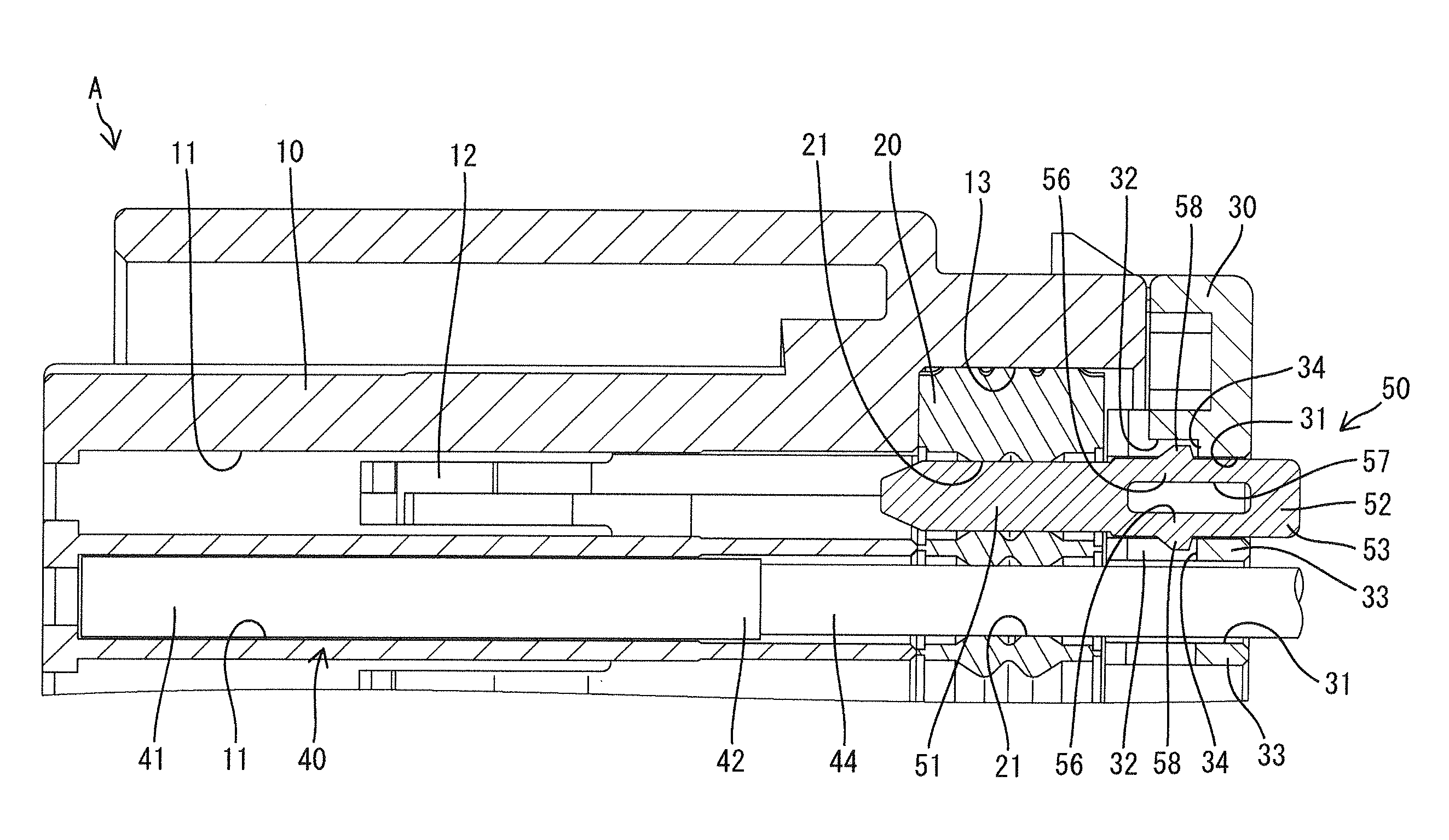
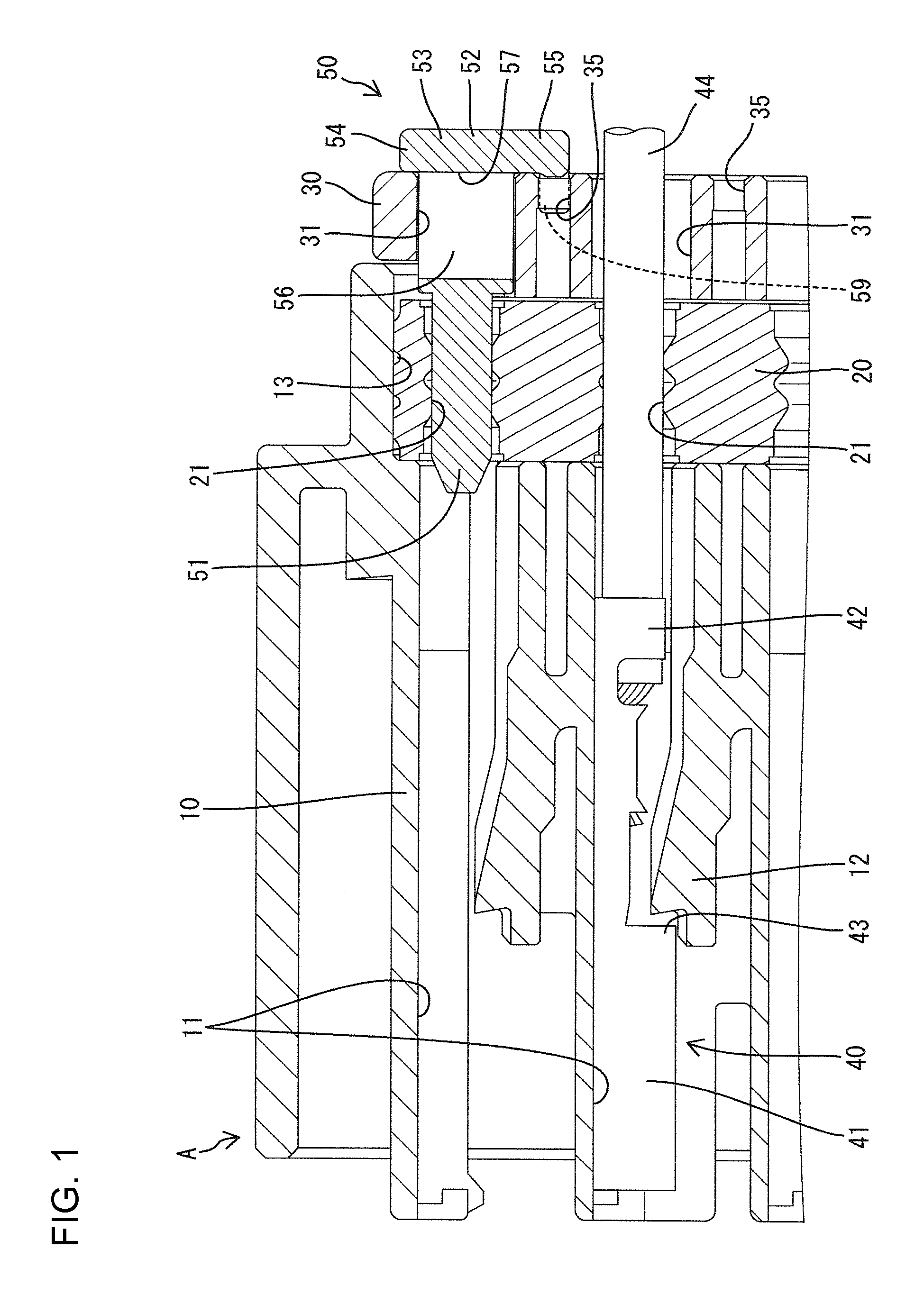
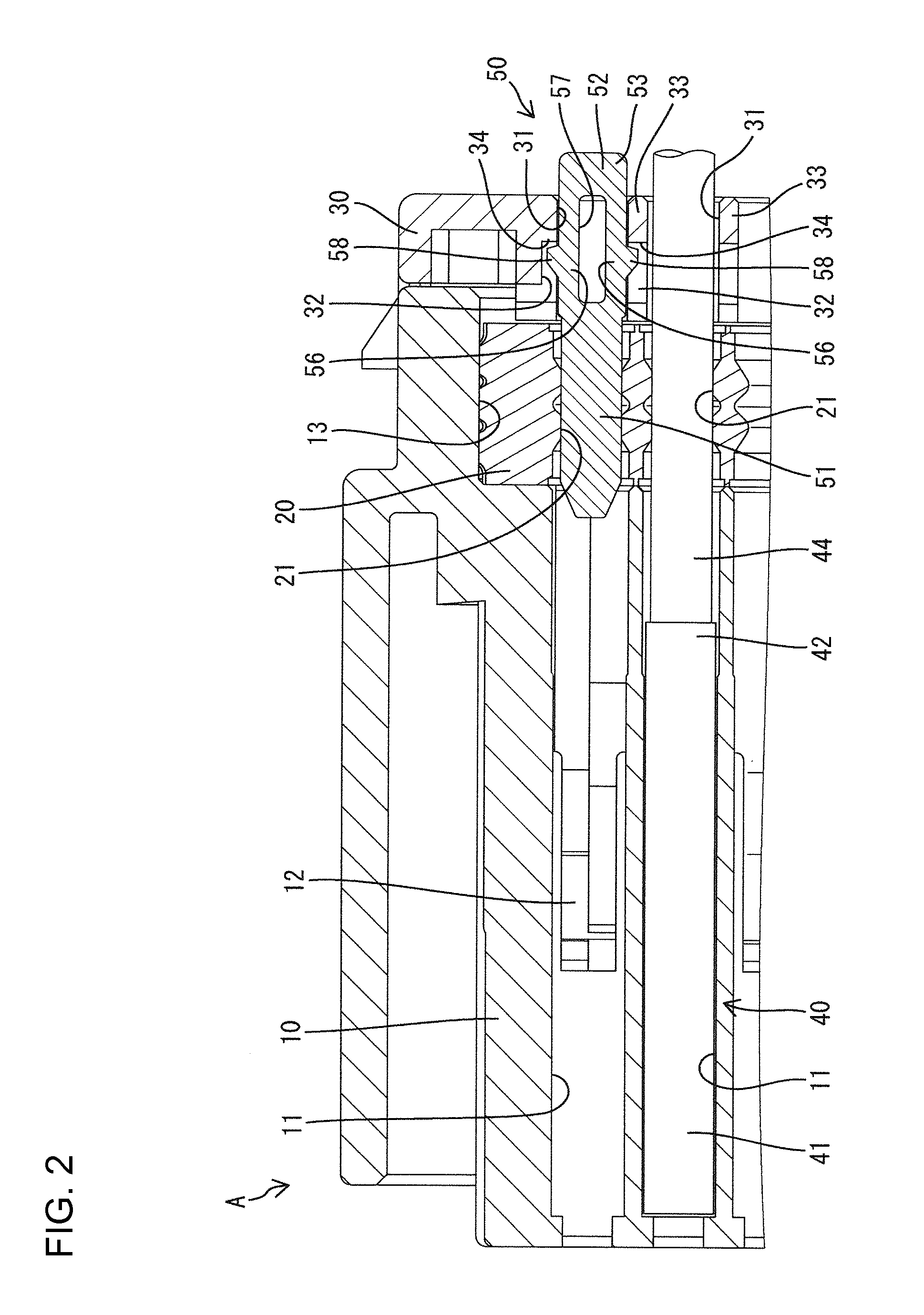
[0021]A connector A in accordance with the invention includes a housing 10, a one-piece rubber plug 20, a holder 30, terminal fittings 40 and a dummy plug 50, as shown in FIGS. 1 and 2.

[0022]The housing 10 is made of synthetic resin and terminal accommodating chambers 11 penetrate the housing 10 in forward and backward directions while being arrayed in vertical and lateral directions. A locking lance 12 is formed unitarily with a lower wall portion of each terminal accommodating chamber 11 and is cantilevered forward (left in FIGS. 1 and 2). Each locking lance 12 is resiliently deformable down in a direction away from the terminal accommodating chamber 11. An accommodating recess 13 is recessed in a rear end of the housing 10 and rear ends of the terminal accommodating chambers 11 are open in the accommodating recess 13.

[0023]The one-piece rubber plug 20 is a thick plate with a plate thickness direction aligned with forward and backward directions, and is mounted into the accommodat...


PUM


Abstract

A dummy plug (50) includes a sealing portion (51) to be fit into a seal hole (21) in a liquid-tight manner when the dummy plug (50) is mounted into a connector (A). A support (53) is arranged behind the sealing portion (51). Two resilient locking pieces (56) link the rear end of the sealing portion (51) and the front end of the support (53) and engage with retaining portions (34) of a holder (30) when the dummy plug (50) is mounted into the connector (A). A single deformation space (57) is provided between the resilient locking pieces (56) and is shared to permit resilient deformations of the resilient locking pieces (56).

Description

BACKGROUND OF THE INVENTION[0001]1. Field of the Invention[0002]The invention relates to a dummy plug.[0003]2. Description of the Related Art[0004]Japanese Unexamined Patent Publication No. 2008-305660 discloses a connector that includes a housing formed with a plurality of terminal accommodating chambers. A one-piece rubber plug is mounted in a rear end portion of the housing and includes a plurality of seal holes corresponding to the terminal accommodating chamber. A holder is arranged behind the one-piece rubber plug and includes a plurality of through holes corresponding to the seal holes. Terminal fittings are inserted through the through holes and the seal holes and into the terminal accommodating chambers.[0005]A dummy plug is mounted in the connector. The dummy plug is long and narrow in forward and backward directions and formed. A waterproof portion is formed at a front end portion of the dummy plug and a plate-like operating portion extends back from the rear end of the w...

Claims


Application Information

Patent Timeline
Patent Type & Authority Applications(United States)
IPC IPC(8): H01R13/40
CPCH01R13/443H01R13/42H01R13/52
Inventor KATAOKA, SHIGETO
Owner SUMITOMO WIRING SYST LTD
Why Eureka
Try Eureka