Sink With Integrated Work Surface

a work surface and sink technology, applied in water installations, cabinets, constructions, etc., can solve the problems of affecting the quality of food, the inability to add extra contamination to the meat, and the inconvenient placement of food at the bottom of the sink

Inactive Publication Date: 2012-09-27
CONLEY DAVID YEPEZ
View PDF18 Cites 0 Cited by
  • Summary
  • Abstract
  • Description
  • Claims
  • Application Information

AI Technical Summary

Problems solved by technology

Unfortunately, current sinks are limited in their design and shape where multiple functions could be supported.
This becomes a problem if the same cutting board, counter top, or any area used for holding and / or cutting meats is used for other tasks and not cleaned beforehand.
It is possible to use the bottom of sinks to prepare raw meat in order to avoid using and contaminating other work surfaces but a problem arrives from this practice in the possibility of adding extra contamination to the meat by microorganisms already existing on the lower surface the sink basin.
Therefore the lower a surface is, the more likely it is to be contaminated by debris from a higher surface making the bottom of a sink a very undesirable location for placing food yet to be consumed.
This activity can easily leave a mess in the areas of operation that will require cleaning in order to make the surface usable for other tasks.
It is difficult to place a large pot under a faucet to fill with water when there is a lack of clearance provided between a divider and a faucet.
It may require placing the pot at the bottom of a sink basin but doing so is unachievable when the basin or basins are already full of dirty dishes.
It is also undesirable since the bottom of the sink basin is typically dirty itself which makes all food and cooking containers that come in contact with that surface dirty as well.
Because hot water must be handled with care it can be problematic trying to hold both a colander and a container of hot water and food at the same time.
Additionally, while pouring the contents of the container into the colander, the liquid would ideally go straight into a sink and drain away without great effort or process; otherwise spilling liquid, especially hot water, in undesirable locations is a nuisance if not calamitous.
This activity produces a significant amount of water droplets that typically drain from holes on the bottom of the spinner.
Several design patents show a lowered divider between two major sink basins but lack the proper proportions for other functions.
Sinks which are combined with cutting and work surfaces are numerous yet they require multiple or separate components incorporated with various moving parts or fasteners which increase cost of construction and susceptibility to malfunction.
D578,184 (2008) with their work surfaces to one side of the sink and open to only one basin instead of between two or more basins is inherently more difficult to clean being that there is only one direction to remove debris during cleaning.
Additionally, having the work and cutting surface far to one side will make it out of reach for most standard sized faucets, making it even more difficult to clean.
Such corrugation or similar patterns may allow for better drainage for washed dishes but inhibit use as a cutting surface and make cleaning away food matter and debris much more difficult than a completely smooth horizontal surface.
This design increases the cost of manufacturing significantly by necessitating both a different separable work surface and intricate fasteners.
The moving parts, besides being more costly to construct, are more susceptible to ware and in some cases rust.
This configuration is therefore inferior and impractical for a variety of work purposes, outside of dish drying, and more difficult to clean.
All these examples suffer from inherently increasing the number of parts and complexity involved in working in a sink setting.
Moreover, moving parts are prone to wear out more quickly.
The deficiency in current designs stems from a problem of inertia in thinking and not recognizing the ubiquity and effectiveness of current technology.

Method used


Image

  • Sink With Integrated Work Surface
  • Sink With Integrated Work Surface
  • Sink With Integrated Work Surface

Examples


Embodiment Construction

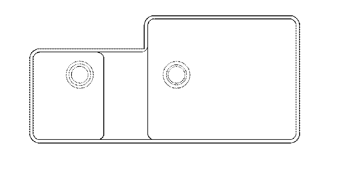
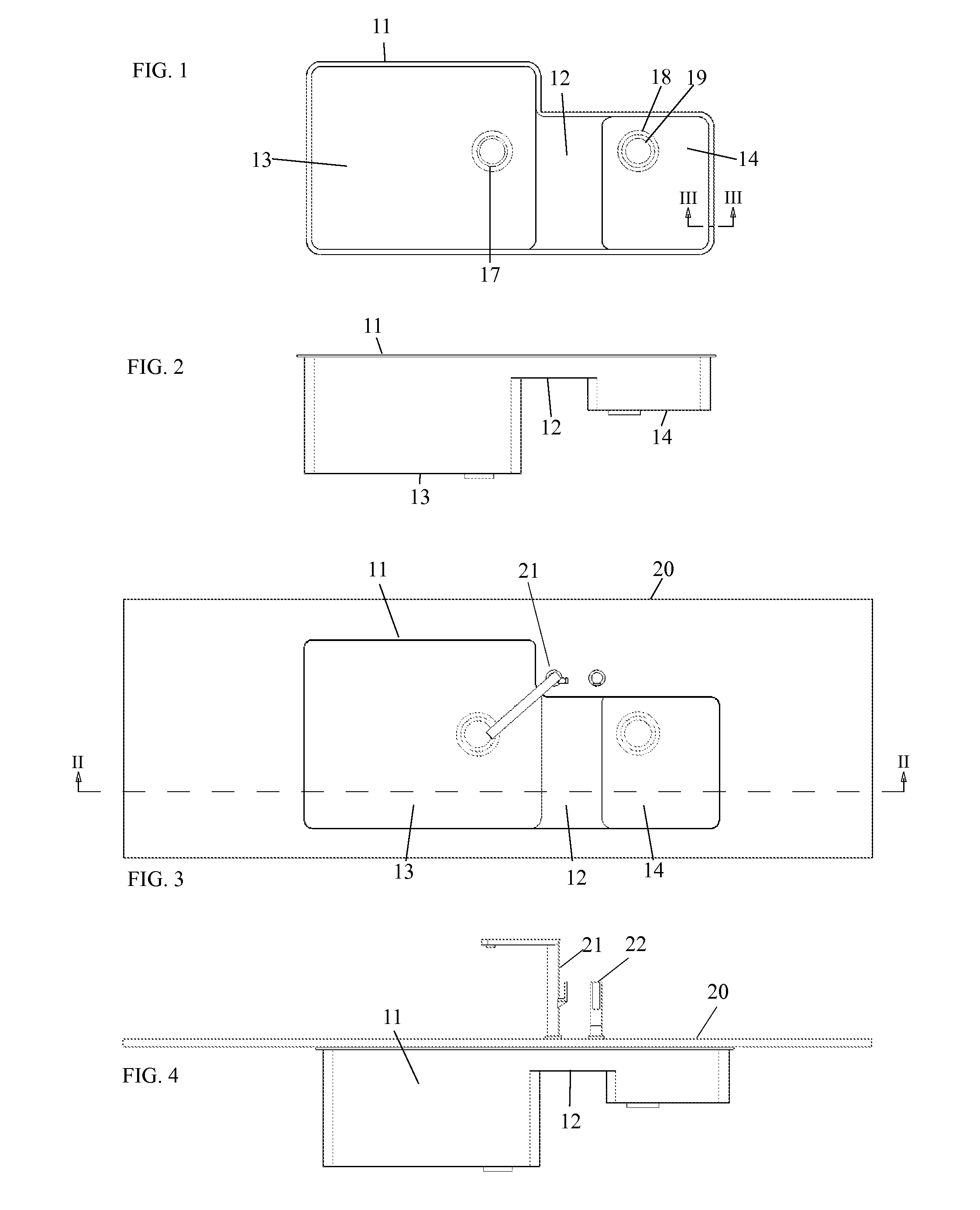
[0035]Referring to the drawings in detail, FIG. 1 illustrates how, as part of the kitchen sink 11, the work surface 12 stands between basin 13 and 14 and spans entirely across the central part of the sink 11 from front to back, thus dividing the two basins 13 and 14 which have their own drains 17 and 18 respectively. A garbage disposal 19 is attached to drain 18 in the first embodiment as shown in FIG. 1.

[0036]In FIG. 2, the multi-purpose work surface12 is shown at a level lower than the top edge of sink 11, but still higher than both sink basins 13 and 14. Having the work surface at a lower level than the top of the edge of the sink helps contain the liquid that will land on and flow over the work surface into the basins. As can be seen in FIG. 2, the form of and around the elevated work surface 12 also serves as the divider between basins 13 and 14.

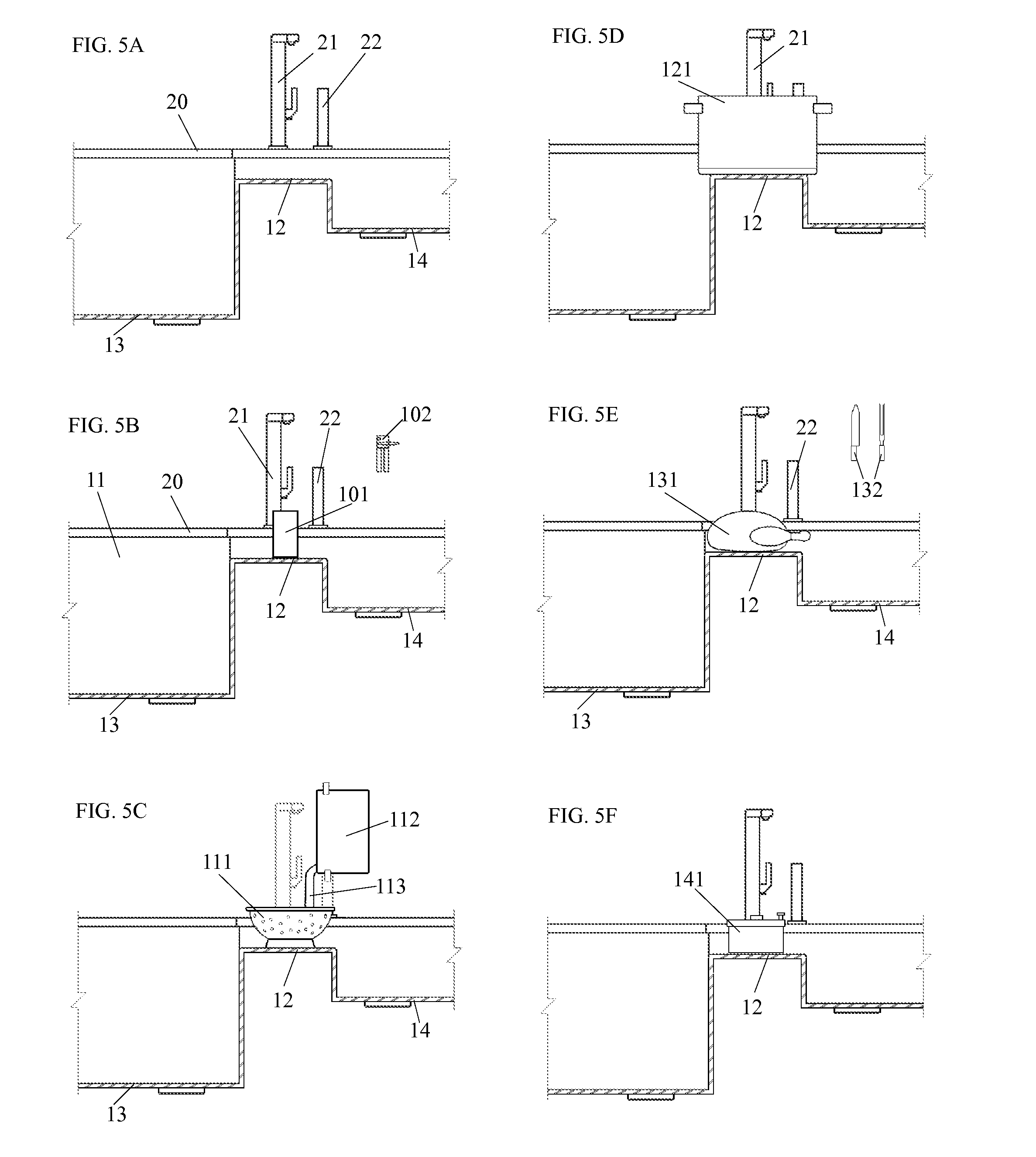
[0037]Sink 11 is connected to an opening in the counter top 20 in FIG. 3. The opening of counter top 10 is shaped as to allow access t...


PUM


Abstract

One embodiment of a sink with an integrally molded work surface area (12) with sink basins (13,14) where the work surface is located between basins and at a level higher than the bottom of the sink basins but lower than the edge of the entire sink unit (11). The work surface provides an area for a range of tasks including can opening, draining with a colander, filling pots with water, preparing and cutting uncooked meats, and operating a salad spinner. The entire combination of sink basins and work surface connects continuously in form to provide a more sanitary and faster food preparation process allowing for the accomplishment of a variety of tasks including easy and simple clean up.

Description

CROSS-REFERENCE TO RELATED APPLICATIONS[0001]Not ApplicableFEDERALLY SPONSORED RESEARCH[0002]Not ApplicableSEQUENCE LISTING OR PROGRAM[0003]Not ApplicableBACKGROUND OF THE INVENTION[0004]1. Field of the Invention[0005]This application relates to sinks, specifically ones used in settings wherever cooking or meal preparation is performed.[0006]2. Prior Art[0007]Both kitchens and sinks have evolved significantly over the last century. Sanitation and convenience have been driving factors in new designs. The kitchen sink has become one of the most important tools in meal preparation and can be used multiple times a day. The primary role of the sink is to provide a sanitary environment, especially important in food preparation. When used in combination with a faucet, sinks can allow water to rinse clean both food items and dirty dishes. They also provide a direct source of water for cooking and drinking. A common design providing these basic tasks is a sink with two basins and a simple di...

Claims


Application Information

Patent Timeline
IPC IPC(8): E03C1/01
CPCA47B77/06E03C1/18
Inventor CONLEY, DAVID YEPEZ
Owner CONLEY DAVID YEPEZ
Why Eureka
Try Eureka