Brake-equipped wheelchair

a brake device and wheelchair technology, applied in the field of brake devices, can solve the problems of low reliability, user forgetting to operate the brake device, wheelchair moving while the user is unprepared, etc., and achieve the effect of smooth release or application

Active Publication Date: 2012-09-27
FRANCE BED
View PDF7 Cites 8 Cited by
  • Summary
  • Abstract
  • Description
  • Claims
  • Application Information

AI Technical Summary

Benefits of technology

[0028]According to the invention, both end portions of a working belt, which includes an intermediate portion disposed on a lower surface side of a seat cushion body, are guided downward of a conveyance body from guide sections of guide bodies which are provided on armrest portions. By the shifting of the working belt, working link mechanism is actuated via a coupling link. Thereby, the brake state of rear wheels by the brake members is released, or the brake is applied.
[0029]Thus, when a user sits on the seat cushion body, which is provided on the seat section such that the seat cushion body is rotatable with a front end portion thereof acting as pivot, and the working belt is pulled against a restoring force of resilient members coupled to both ends of the working belt, or when the user rises from the seat cushion body and the working belt is pulled by the restoring force of the resilient members, the direction of movement of the working belt can be made closer to the direction of rotation of the seat cushion body.
[0030]When the direction of movement of the working belt becomes closer to the direction of rotation of the seat cushion body, the working belt smoothly moves along the guide sections, and the brake members move in interlock with the movement of the working belt. Therefore, the brake by the brake members can smoothly be released or applied.
[0031]Furthermore, since the shift of the working belt is transmitted to the working link mechanism via the coupling link and the brake member is shifted by the operation of the working link mechanism, the brake member can surely be operated.
[0032]FIG. 1 is a perspective view of a wheelchair according to a first embodiment of the invention.
[0033]FIG. 2 is a perspective view showing a seat section of the wheelchair, as viewed from above.

Problems solved by technology

According to this structure, when the user rises from the seat section and gets out of the wheelchair, there may be a case that the wheelchair moves while the user is unprepared.
However, in the case of the manual brake device, it is possible that the user forgets to operate the brake device, and the reliability is low.

Method used


Image

  • Brake-equipped wheelchair
  • Brake-equipped wheelchair
  • Brake-equipped wheelchair

Examples


example 1

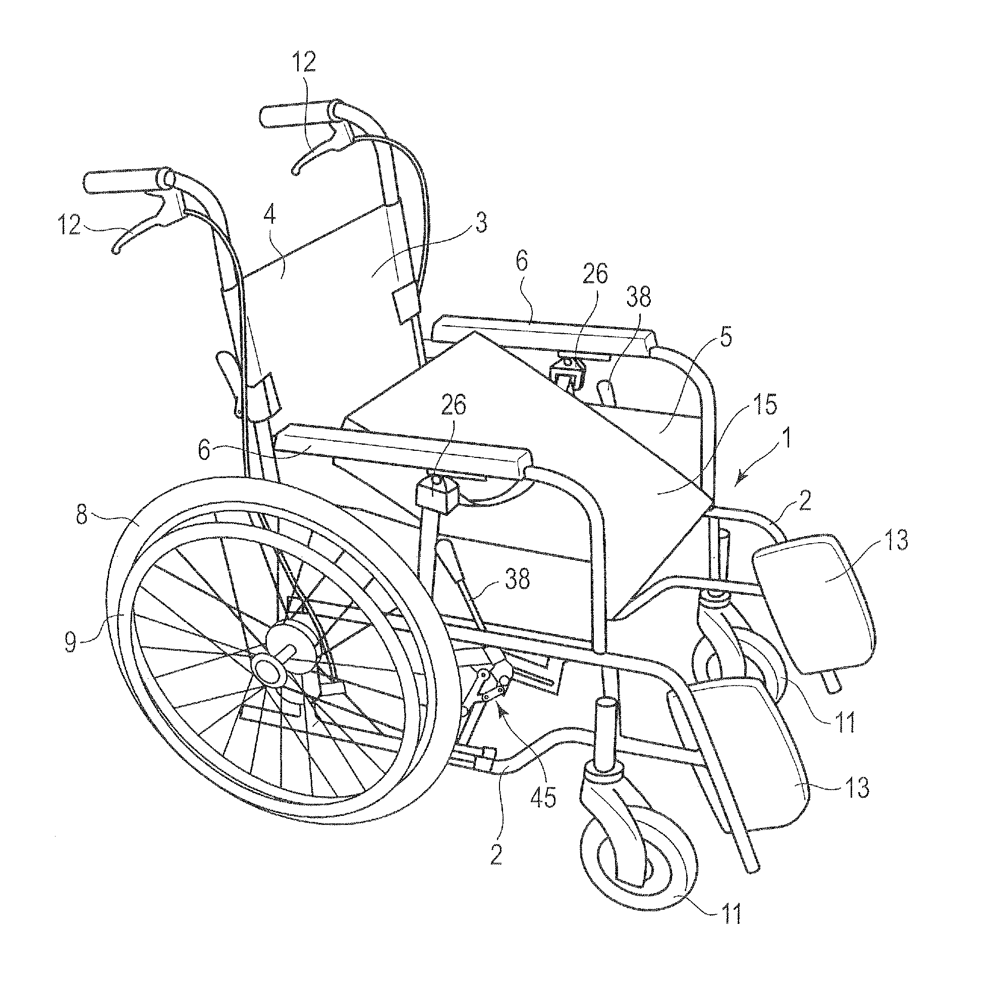
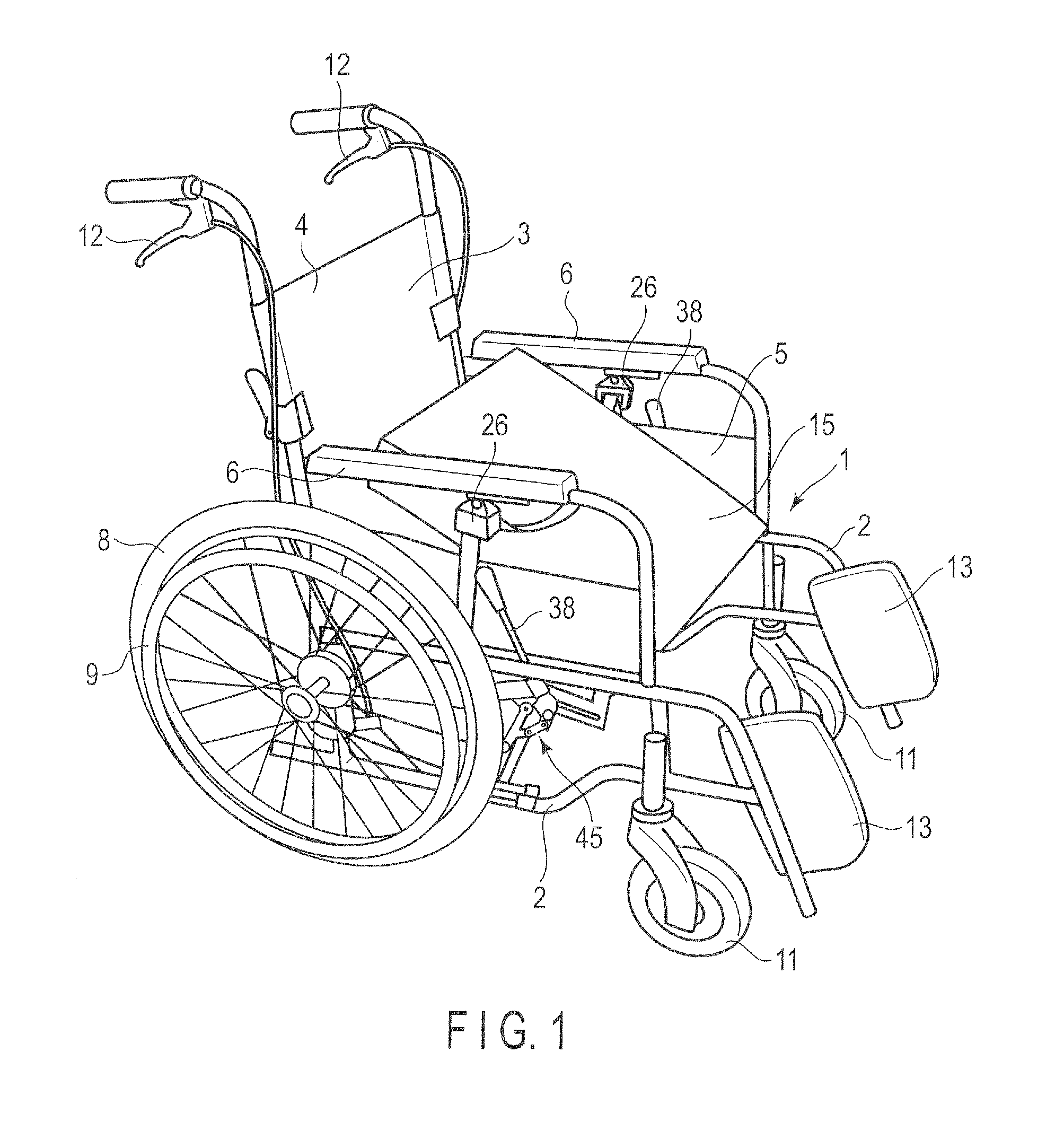
[0052]FIG. 1 to FIG. 10 show a first embodiment of the invention. FIG. 1 is a perspective view showing brake-equipped wheelchair. This wheelchair includes a conveyance body 1. The conveyance body 1 is constructed such that a pair of side frames 2, which are formed of pipe materials, are coupled with a predetermined distance. A cloth sheet 3 is provided between the side frames 2. Thereby, a back section 4 and a seat section 5 are formed in the conveyance body 1. Further, armrest portions 6 are formed on both sides of the seat section 5.

[0053]The sheet 3 includes a part provided on the back section 4 and a part provided on the seat section 5, which are divided at a part corresponding to a lower end of the back section 4 and a rear end of the seat section 5.

[0054]A pair of rear wheels 8 (only one rear wheel is illustrated) are rotatably provided at rear end portions on both sides of the conveyance body 1. Auxiliary wheels 9, which are smaller in diameter than the rear wheels 8, are int...

example 2

[0101]FIG. 11 to FIG. 13 show a second embodiment of the invention, which illustrates a modification of the working link mechanism. The same parts as in the first embodiment are denoted by like reference numerals, and a description thereof is omitted.

[0102]As shown in FIG. 11, a working link mechanism 45A of the second embodiment includes a coupling link 136 having one end pivotally attached to the coupling member 33 of the led-out portion 25a of the working belt 25. A bent portion 136a, which is bent upward, is formed at the other end portion of the coupling link 136.

[0103]The part of the bent portion 136a is pivotally attached via a support shaft 51 to a plate 39 which is provided on a lower surface of the seat section 5 of the conveyance body 1, with the plate surface of the plate 39 being vertically disposed. One end of pressing piece 52 is provided at a distal end portion of the bent portion 136a of the coupling link 136, such that the one end of the pressing piece 52 is resili...

example 3

[0121]FIG. 14 shows a modification of the guide body 26 according to a third embodiment of the invention. In this embodiment, the guide roller 29 is not provided in the guide body 26. Instead, a flat-shaped through-hole 61 for passing the working belt 25 is provided in the swinging member 28 of the guide body 26. In the through-hole 61, a surface, which is brought into contact with the working belt 25, is formed as a convex arcuate surface.

[0122]In the case where the through-hole 61 is formed in the swinging member 28 of the guide body 26, the guide body 26 may be swingably provided on the armrest portion 6, or the guide body 26 may be fixedly provided such that the through-hole 61 is inclined to be raised at a predetermined angle toward the rear side of the conveyance body 1.

[0123]Although not illustrated, without providing the swing member 28 on the conveyance body 1, a through-hole may be formed in the armrest portion 6 and the working belt 25 may be passed through the through-ho...


PUM


Abstract

Coupling links coupled at one end to terminal ends of the working belt and rotatably coupled at the other end to the conveyance body, the coupling links being configured to rotate when the seat cushion body rotates with a front end portion thereof acting as a pivot and both end portions of the working belt move in an up-and-down direction, and a working link mechanism provided in a manner to operate in interlock with the rotation the coupling link, the working link mechanism being configured to shift a brake member in accordance with a direction of rotation of the coupling link into a state that the brake member is separated from a rear wheel to release braking, or into such a state that the brake member is brought into contact with the rear wheel to apply braking.

Description

CROSS REFERENCE TO RELATED APPLICATIONS[0001]This application is a Continuation Application of PCT Application No. PCT / JP2011 / 073418, filed Oct. 12, 2011 and based upon and claiming the benefit of priority from prior Japanese Patent Applications No. 2010-261423, filed Nov. 24, 2010; and No. 2011-176678, filed Aug. 12, 2011, the entire contents of all of which are incorporated herein by reference.BACKGROUND OF THE INVENTION[0002]1. Field of the Invention[0003]The present invention relates to a brake-equipped wheelchair wherein the rotation of rear wheels is prevented by brake members when a user rises from a seat section.[0004]2. Description of the Related Art[0005]For example, a wheelchair for nursing-care or for use by a physically handicapped person includes a conveyance body which is provided with front wheels and rear wheels, and a back section and a seat section are formed in the conveyance body. When a user sits on the seat section, the wheelchair is moved by a helper pushing ...

Claims


Application Information

Patent Timeline
Patent Type & Authority Applications(United States)
IPC IPC(8): B62B5/04
CPCA61G5/022A61G5/1018A61G5/1035A61G2005/1091A61G5/14A61G2005/1054A61G5/1037A61G5/1054A61G5/1091A61G5/02A61G5/10B60T7/14
Inventor OOYAMA, KEI
Owner FRANCE BED
Why Eureka
Try Eureka