Eureka AIR delivers breakthrough ideas for toughest innovation challenges, trusted by R&D personnel around the world.

Bending apparatus for rod-shaped workpieces

a technology for bending apparatus and workpieces, which is applied in the direction of metal-working feeding devices, metal-working storage devices, positioning devices, etc., can solve the problems of limiting the available bending space, requiring a large amount of overall space for bending installation, and a considerable interference of cutting devices

Active Publication Date: 2013-10-22
WAFIOS AKTIENGES
View PDF19 Cites 7 Cited by
  • Summary
  • Abstract
  • Description
  • Claims
  • Application Information

AI Technical Summary

Benefits of technology

[0011]In an embodiment, not only the cutting device but also the upstream feed device that can be displaced in the direction of feed of the workpiece (and thus also against the same) in an embodiment in accordance with the invention, the cutting device and the feed device can be driven away from the bending head to a predetermined position which is remote from the same as far as possible, so that much space is available between the cutting device and the bending head for turning down a long leg of a bending part (workpiece). As a result of the displaceability of the feed device as provided in accordance with the invention, it can be ensured that the cutting device can also be displaced especially far away from the bending head.
[0012]If workpieces are to be bent where it is intended that only a relatively short straight end piece remains between bending head and cutting device, which is often desirable, the cutting device can be displaced close to and adjacent to the bending head through the displaceability of the cutting device independent of the feed device without requiring a displacement of the feed device at the same time, e.g. from a position remote from the bending head for example. If further the shortest possible distance between the feed device and the bending head is also to be ensured in order to prevent undesirable deformations in this area, especially in the case of processing thin wires, the feed device can be displaced to a position moved very close to the bending head in the case of a cutting device that has been moved entirely up to the bending head.
[0014]An embodiment of the bending apparatus in accordance with the invention is that the cutting device and the feed device are each displaceable on a separate guideway, with the guideways being disposed parallel next to one another. This embodiment offers the possibility of enabling an especially close travel of the feed device to the mandrel (in its extreme forward position) through a suitable arrangement of cutting device and feed device. Only the section of the displaceable cutting device which performs the cut is disposed between feed device and bending head, which cutting device is still interposed also in the extreme forward position between bending head and feed device, and the remaining part of the cutting device, including the motor for the process, can be arranged among other things laterally adjacent to the feed device and parallel to the same. It is thus possible to realize an especially short straight end piece of the workpiece between cutting point and bending head. It is advantageous when each guideway comprises two parallel guide strips, so that storage and displaceability can occur in each case on two parallel rails both in the cutting device and in the feed device, contributing to an especially low-vibration and stable overall construction.
[0017]An embodiment of the invention is also that the cutting device comprises a base plate from which a support arm which holds a movable cutting knife and a fixed counter-knife for performing a cut protrudes into the feed axis of the respectively conveyed workpiece that the workpiece coming from the feed device extends between the two knives. Since the two knives are attached in this case on a protruding support arm, this provides the possibility to allow only this support arm with the knives to protrude into the feed axis of the workpiece and to otherwise allow the arm to run out of the feed axis of the workpiece, so that the motor for driving the knives and the carriage as well as the motor for displacing the cutting device can be attached at a distance from the feed axis of the workpiece. This allows the feed device to move very closely to the bending head in its extreme forward position, so that only the width of the support arm with the two knives is interposed between itself and the bending head, thus resulting in especially short straight end pieces of the workpiece after the cut.
[0020]A further embodiment of the invention is that the feed device is associated upstream with an aligning device which can be jointly moved with the same (with the term “upstream” and “downstream” being used herein always within the sense of a reference to the direction of transport of the supplied workpiece). This leads to the advantage that during a return travel of the feed device the workpiece need not be pushed back by the aligning device which is upstream of the same.

Problems solved by technology

A further cutting device, which is stationary however, is attached between the feed device and the bending head, which cutting device represents a considerable interference contour however when a long leg is to be bent by more than 90°.
This known bending installation requires overall a lot of space.
Moreover, the bending head or bending heads rotate about the workpiece and considerably limit the available bending space.
Moreover, a relatively long straight end piece also remains between the cut and the bending head in the construction as described there, which is also often undesirable.
As a result of the length of the folding shank, this always leads to the consequence that there will always be a relatively long straight end piece of the workpiece between the cutting point and the bending head, which is often undesirable.
A relatively long straight end piece of the workpiece remains in this known bending machine too between cutting point and bending head, with there also always being a very large distance between the feed unit and the bending head which may lead to difficulties especially in processing very thin wires.

Method used


Image

  • Bending apparatus for rod-shaped workpieces
  • Bending apparatus for rod-shaped workpieces
  • Bending apparatus for rod-shaped workpieces

Examples


Embodiment Construction

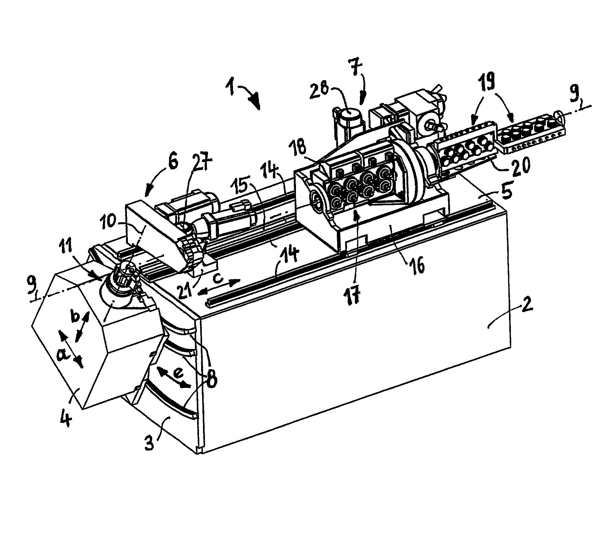
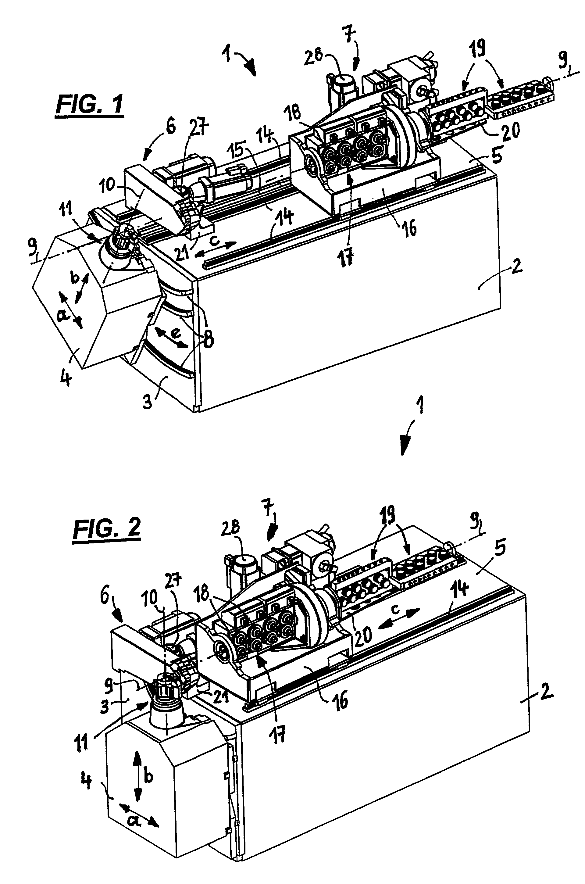
[0028]FIGS. 1 and 2 show a perspective view diagonally from above of a bending machine 1, comprising a machine frame 2, a bending head 4 attached to the face side 3 of the same and a cutting device 6 attached to the upper side 5 of the machine frame 2 and a feed and aligning device 7.

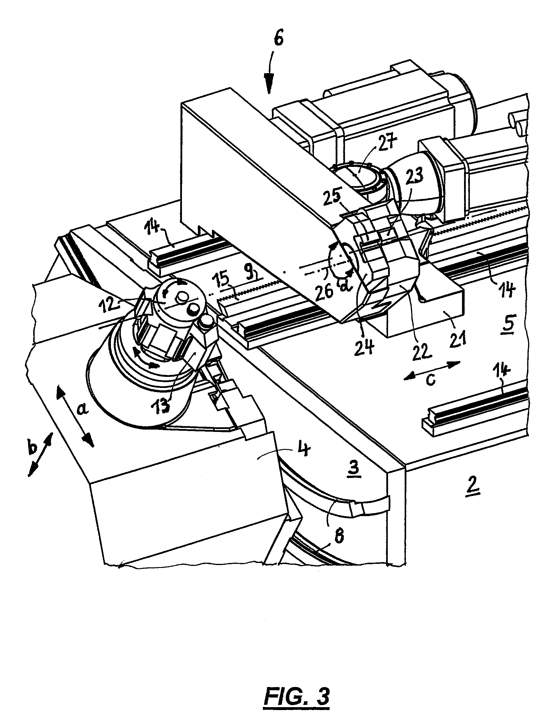
[0029]The bending head 4 sits on arc-shaped curved guide strips (curved guides) 8 which are arranged and configured in such a way that their central point of curvature lies in the central axis 9 of the supplied workpiece. During a lateral swiveling of the bending head 4 along the curved guides 8, a swiveling movement of the bending head 4 about the center of the workpiece is thus achieved, i.e. about the central axis 9 of the workpiece (swiveling movement e, cf. FIG. 1).

[0030]The bending head 4 is usually pre-positioned in a certain alignment and no longer swiveled during the ongoing production. There is still a possibility however to also swivel the bending head during the production process in the dir...


PUM

PropertyMeasurementUnit
travel distanceaaaaaaaaaa
lengthaaaaaaaaaa
displacementaaaaaaaaaa

Abstract

In a bending apparatus for rod-shaped workpieces, comprising a machine frame to which a bending head with bending tools is attached, which bending head is movable relative to the frame, further a feed device upstream of the bending head for feeding the workpieces to the same, and a cutting device which can be displaced in the direction of feed of the workpieces and can be applied between bending head and feed device to the respective workpiece for cutting the same, the feed device can also be displaced in the direction of feed of the workpiece in addition to the cutting device, which occurs independent of the displacement of the cutting device.

Description

[0001]This application claims priority to German Patent Application No. 10 2009 024 075.6 filed on Jun. 5, 2009, said application is incorporated herein by reference in it's entirety.FIELD OF THE INVENTION[0002]The invention relates to a bending apparatus for rod-shaped workpieces.BACKGROUND OF THE INVENTION[0003]It is principally desirable in bending apparatuses and especially such for bending rod-shaped workpieces to have the largest possible bending space so that there is also sufficient space for example for turning down the longest possible leg of a bending part when bending needs to be produced which is larger than 90° without parts of the bending machine representing an interference contour.[0004]A bending machine is known from DE 602 19 651 T2 (corresponding to EP 1 434 660 B1) in which a feed device and two cutting devices are provided upstream of the bending head, one of which is fastened to the frame of the feed device and is displaceable with the same in the direction of...

Claims


Application Information

Patent Timeline
Patent Type & Authority Patents(United States)
IPC IPC(8): B21D11/00
CPCB21D7/12B21D11/12B21F1/00B21F1/006
Inventor VEIT, GUSTAVWIEBLEN, FRANK
Owner WAFIOS AKTIENGES
Why Eureka
Eureka Blog
Learn More