Hinged drumstick

a technology of drumsticks and hammers, which is applied in the field of hammers, can solve the problems of reducing the rattling of the at least one grasping mechanism within the body. it is reduced and/or minimized

Inactive Publication Date: 2015-04-21
HINGESTIX
View PDF35 Cites 6 Cited by
  • Summary
  • Abstract
  • Description
  • Claims
  • Application Information

AI Technical Summary

Benefits of technology

[0009]According to one aspect, the present invention is directed to a percussion instrument that may include a body having a longitudinal axis extending from a butt end to a striking end thereof and at least two holes extending through the thickness of the body substantially along and / or through a respective axis that is different from the longitudinal axis and that is different from the axis of the other hole of the at least two holes; at least one grasping mechanism having a first grip plate at a first end thereof and a second grip plate at a second end thereof, at least one shaft extending from the first grip plate through a first hole of the at least two holes in the body to the second grip plate, and a releasable connection between the first grip plate and the second grip plate such that the at least one grasping mechanism operates to be positioned in the first hole of the at least two holes and the first grip plate and the second grip plate operate to be disconnected from each other and / or connected / re-connected to each other such that the at least one grasping mechanism operates to be positioned in a second hole of the at least two holes and / or re-positioned in the first hole of the at least two holes; and a compliance mechanism disposed between the first and second grip plates, enabling the first and second grip plates to be moved closer together in response to a compressive force applied to the at least one grasping mechanism.
[0016]The first hole of the at least two holes and / or the second hole of the at least two holes may be sized and shaped to operate to at least one of: permit the at least one grasping mechanism and / or the compliance mechanism to be positioned therein such that a zone of space of a predetermined size is located between the first hole of the at least two holes and / or the second hole of the at least two holes and the at least one grasping mechanism and / or the compliance mechanism, thereby permitting the at least one grasping mechanism and / or the compliance mechanism to move freely within the first hole of the at least two holes and / or the second hole of the at least two holes; permit the at least one grasping mechanism and / or the compliance mechanism to be positioned therein such that a zone of space of a predetermined size is located between the first hole of the at least two holes and / or the second hole of the at least two holes and the at least one grasping mechanism and / or the compliance mechanism, thereby permitting the at least one grasping mechanism and / or the compliance mechanism to move freely in at least a direction that is substantially along the length of the first hole of the at least two holes and / or the second hole of the at least two holes within the first hole of the at least two holes and / or the second hole of the at least two holes; permit the at least one grasping mechanism and / or the compliance mechanism to be positioned therein and to be spaced away therefrom such that the at least one grasping mechanism and / or the compliance mechanism operates to make one or more audible noises when hitting against the first hole of the at least two holes and / or the second hole of the at least two holes, thereby permitting the at least one grasping mechanism and / or the compliance mechanism to move freely within the first hole of the at least two holes and / or the second hole of the at least two holes; permit the at least one grasping mechanism and / or the compliance mechanism to be positioned therein and to be spaced away therefrom such that the at least one grasping mechanism and / or the compliance mechanism operates to make one or more audible noises when hitting against the first hole of the at least two holes and / or the second hole of the at least two holes, thereby permitting the at least one grasping mechanism and / or the compliance mechanism to move freely in at least a direction that is substantially along the length of the first hole of the at least two holes and / or the second hole of the at least two holes within the first hole of the at least two holes and / or the second hole of the at least two holes; and permit the at least one grasping mechanism and / or the compliance mechanism to be positioned therein and to be in contact with at least a portion thereof.
[0027]The first hole of the at least two holes and / or the second hole of the at least two holes may be sized and shaped to operate to at least one of: permit the at least one grasping mechanism to be positioned therein such that a zone of space of a predetermined size is located between the first hole of the at least two holes and / or the second hole of the at least two holes and the at least one grasping mechanism, thereby permitting the at least one grasping mechanism to move freely within the first hole of the at least two holes and / or the second hole of the at least two holes; permit the at least one grasping mechanism to be positioned therein such that a zone of space of a predetermined size is located between the first hole of the at least two holes and / or the second hole of the at least two holes and the at least one grasping mechanism, thereby permitting the at least one grasping mechanism to move freely in at least a direction that is substantially along the length of the first hole of the at least two holes and / or the second hole of the at least two holes within the first hole of the at least two holes and / or the second hole of the at least two holes; permit the at least one grasping mechanism to be positioned therein and to be spaced away therefrom such that the at least one grasping mechanism operates to make one or more audible noises when hitting against the first hole of the at least two holes and / or the second hole of the at least two holes, thereby permitting the at least one grasping mechanism to move freely within the first hole of the at least two holes and / or the second hole of the at least two holes permit the at least one grasping mechanism to be positioned therein and to be spaced away therefrom such that the at least one grasping mechanism operates to make one or more audible noises when hitting against the first hole of the at least two holes and / or the second hole of the at least two holes, thereby permitting the at least one grasping mechanism to move freely in at least a direction that is substantially along the length of the first hole of the at least two holes and / or the second hole of the at least two holes; and permit the at least one grasping mechanism to be positioned therein and to be in contact with at least a portion thereof.
[0037]The first hole of the at least two holes and / or the second hole of the at least two holes may be sized and shaped to operate to at least one of: permit the at least one hinge to be positioned therein such that a zone of space of a predetermined size is located between the first hole of the at least two holes and / or the second hole of the at least two holes and the at least one hinge, thereby permitting the at least one hinge to move freely within the first hole of the at least two holes and / or the second hole of the at least two holes; permit the at least one hinge to be positioned therein such that a zone of space of a predetermined size is located between the first hole of the at least two holes and / or the second hole of the at least two holes and the at least one hinge, thereby permitting the at least one hinge to move freely in at least a direction that is substantially along the length of the first hole of the at least two holes and / or the second hole of the at least two holes within the first hole of the at least two holes and / or the second hole of the at least two holes; permit the at least one hinge to be positioned therein and to be spaced away therefrom such that the at least one hinge operates to make one or more audible noises when hitting against the first hole of the at least two holes and / or the second hole of the at least two holes, thereby permitting the at least one hinge to move freely within the first hole of the at least two holes and / or the second hole of the at least two holes; permit the at least one hinge to be positioned therein and to be spaced away therefrom such that the at least one hinge operates to make one or more audible noises when hitting against the first hole of the at least two holes and / or the second hole of the at least two holes, thereby permitting the at least one hinge to move freely in at least a direction that is substantially along the length of the first hole of the at least two holes and / or the second hole of the at least two holes within the first hole of the at least two holes and / or the second hole of the at least two holes; and permit the at least one hinge to be positioned therein and to be in contact with at least a portion thereof.

Problems solved by technology

When held too tightly there is too much friction, and the player inhibits the motion (rebound) of the drumstick.
However, such designs do not establish freedom from restraint in pivotal movement as the stick rebounds from the drum.
Moreover, they do not facilitate grasping and control of the drumstick at the balance point, especially for the student learning the fingertip control method of playing drums.
Such a configuration caused the drum to tilt at an angle whereby having the left hand on top of the stick (like the right hand for the other corresponding drumstick) would cause the drummer's elbow to stick out in the air and cause fatigue.
Thus, it is a problem in the art that prior approaches to providing unrestrained pivotal motion of the drumstick do not also enable a user to exercise sufficient control over the drumstick.
An additional problem is that one stick does not exist that permits users thereof to exercise sufficient control over the drumstick while performing multiple types of drumming styles, such as, but not limited to, the traditional, left hand gripping style; the right hand, matched gripping style; the French style; etc.

Method used


Image

  • Hinged drumstick
  • Hinged drumstick
  • Hinged drumstick

Examples


Embodiment Construction

[0064]In the following description, for purposes of explanation, specific numbers, materials and configurations are set forth in order to provide a thorough understanding of the invention. It will be apparent, however, to one having ordinary skill in the art that the invention may be practiced without these specific details. In some instances, well-known features may be omitted or simplified so as not to obscure the present invention. Furthermore, reference in the specification to phrases such as “one embodiment” or “an embodiment” means that a particular feature, structure or characteristic described in connection with the embodiment is included in at least one embodiment of the invention. The appearances of phrases such as “in one embodiment” or “in an embodiment” in various places in the specification do not necessarily all refer to the same embodiment.

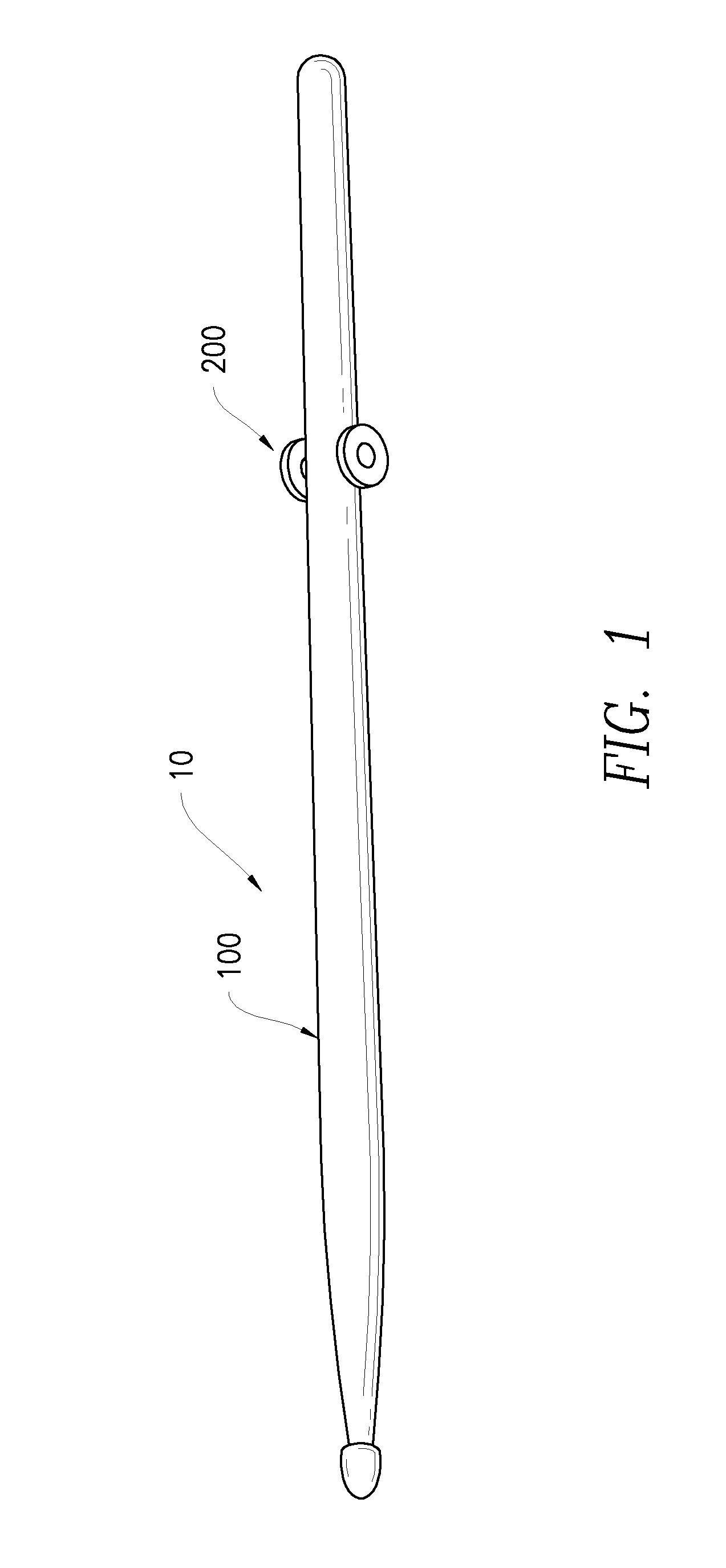
[0065]FIG. 1 is a perspective view of a drumstick 10 in accordance with an embodiment of the present invention. The drumstick 10 ...


PUM


Abstract

A percussion instrument is disclosed that may include a body having a longitudinal axis extending from a butt end to a striking end thereof and at least one hole extending through the thickness of the body substantially along or through an axis that is different from the longitudinal axis; and a grasping mechanism having a first grip plate at a first end thereof and a second grip plate at a second end thereof, and at least one shaft extending through the hole. The percussion instrument may further include a compliance mechanism disposed between the first and second grip plates, enabling the first and second grip plates to move closer together in response to a compressive force applied. One or more recesses or bores may be used for a more compact design, and the at least one hole may be on an angle to accommodate different drumming styles.

Description

CROSS-REFERENCE TO RELATED APPLICATIONS[0001]This application is a Continuation-in-Part of U.S. Non-Provisional patent application Ser. No. 13 / 772,837, filed Feb. 21, 2013, and presently pending, which is a Continuation-in-Part of U.S. Non-Provisional patent application Ser. No. 13 / 314,244, filed Dec. 8, 2011, and presently pending, entitled “Hinged Drumstick”, which is a Continuation-in-Part of U.S. Non-Provisional patent application Ser. No. 12 / 774,408, filed May 5, 2010, entitled “Hinged Drumstick”, which has issued as U.S. Pat. No. 8,253,003 on Aug. 28, 2012, and which is a Continuation-in-Part of U.S. Non-Provisional application Ser. No. 12 / 610,670, filed Nov. 2, 2009, entitled “Hinged Drumstick” which application has issued as U.S. Pat. No. 7,897,859 on Mar. 1, 2011, and claims the benefit of U.S. Provisional Patent Application Ser. No. 61 / 184,467, filed Jun. 5, 2009, entitled “Ruttenberg's Hinge Drumstick”, the entire disclosures of which applications and patents are hereby i...

Claims


Application Information

Patent Timeline
Patent Type & Authority Patents(United States)
IPC IPC(8): G10D13/02G10D13/00
CPCG10D13/003G10D13/12
Inventor RUTTENBERG, SAMUEL
Owner HINGESTIX
Why Eureka
Try Eureka