Refractive index distribution measuring method and refractive index distribution measuring apparatus

a technology of refractive index and measuring method, which is applied in the direction of optical apparatus testing, applications, instruments, etc., can solve the problems of time-consuming adjustment and different refractive index distribution

Active Publication Date: 2012-09-27
CANON KK
View PDF7 Cites 18 Cited by
  • Summary
  • Abstract
  • Description
  • Claims
  • Application Information

AI Technical Summary

Benefits of technology

[0005]The present invention provides a refractive index distribution measuring method and a refractive index distribution measuring method apparatus, which can quickly and highly precisely measure a refractive index distribution of a test object in a nondestructive state.

Problems solved by technology

The working of the test object is time-consuming, and changes the internal stress of the test object and thus its internal refractive index distribution before and after the working, thereby causing a refractive index distribution to be different from the pre-working refractive index distribution.
An adjustment of the refractive index of the matching oil requires a blend of different types of oils and this adjustment is time-consuming.

Method used


Image

  • Refractive index distribution measuring method and refractive index distribution measuring apparatus
  • Refractive index distribution measuring method and refractive index distribution measuring apparatus
  • Refractive index distribution measuring method and refractive index distribution measuring apparatus

Examples


first embodiment

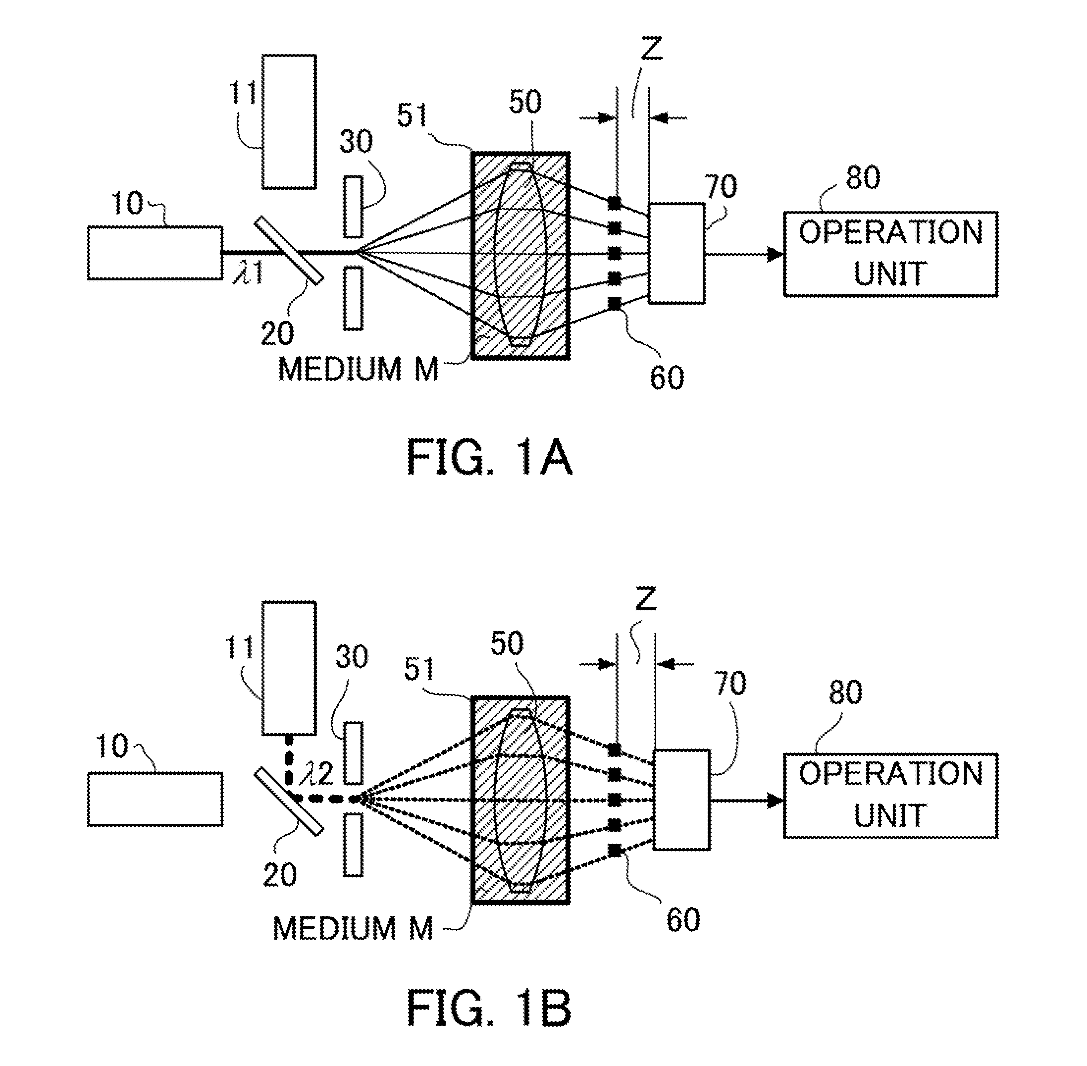
[0014]A description will now be given of a refractive index distribution measuring apparatus that executes a refractive index distribution measuring method according to a first embodiment. The refractive index distribution measuring apparatus measures a transmitted wavefront of a test object by immersing the object in a medium (M) having a refractive index different from that of the test object and by introducing two types of reference beams, such as light of a first wavelength and light of a second wavelength, into the object. The refractive index distribution measuring apparatus then calculates a refractive index distribution of the test object utilizing a measurement result of the transmitted wavefront. The test object is a lens (optical element) having a positive power.

[0015]FIG. 1 is a block diagram of a Talbot interferometer as a measuring unit configured to measure the transmitted wavefront of the test object 50 utilizing two beams having different wavelengths. A side surface...

second embodiment

[0074]In a second embodiment, a measuring unit other than the interferometer is used for measurements of a test object having a negative power. Those elements in this embodiment, which are the corresponding elements in the first embodiment, will be designated by the same reference numerals.

[0075]FIG. 4 is a block diagram of a measuring apparatus of this embodiment. The test object 50 is a lens (optical element) having a negative power. The medium M filled in a space around the test object 50 is, for example, water (although FIG. 4 illustrates it as a medium).

[0076]A light source 12 is configured to simultaneously emit beams of two types of wavelengths, such as a multimode oscillating laser (e.g., a fundamental wave and a second harmonic of a YAG laser) or a combination of a broadband light source (e.g., a Supercontinuum light source) and a specific wavelength-selective filter. Shack-Hartman sensors 71a, 71b are used to measure transmitted wavefronts.

[0077]The light having the first ...

third embodiment

[0088]A third embodiment discusses a refractive index distribution measuring apparatus that can omit decentering, inclining, and adjusting a position in the optical axis direction of the test object, which are necessary for the first and second embodiments. Those elements in this embodiment, which are the same as corresponding elements in the first and second embodiments, are designated by the same reference numerals.

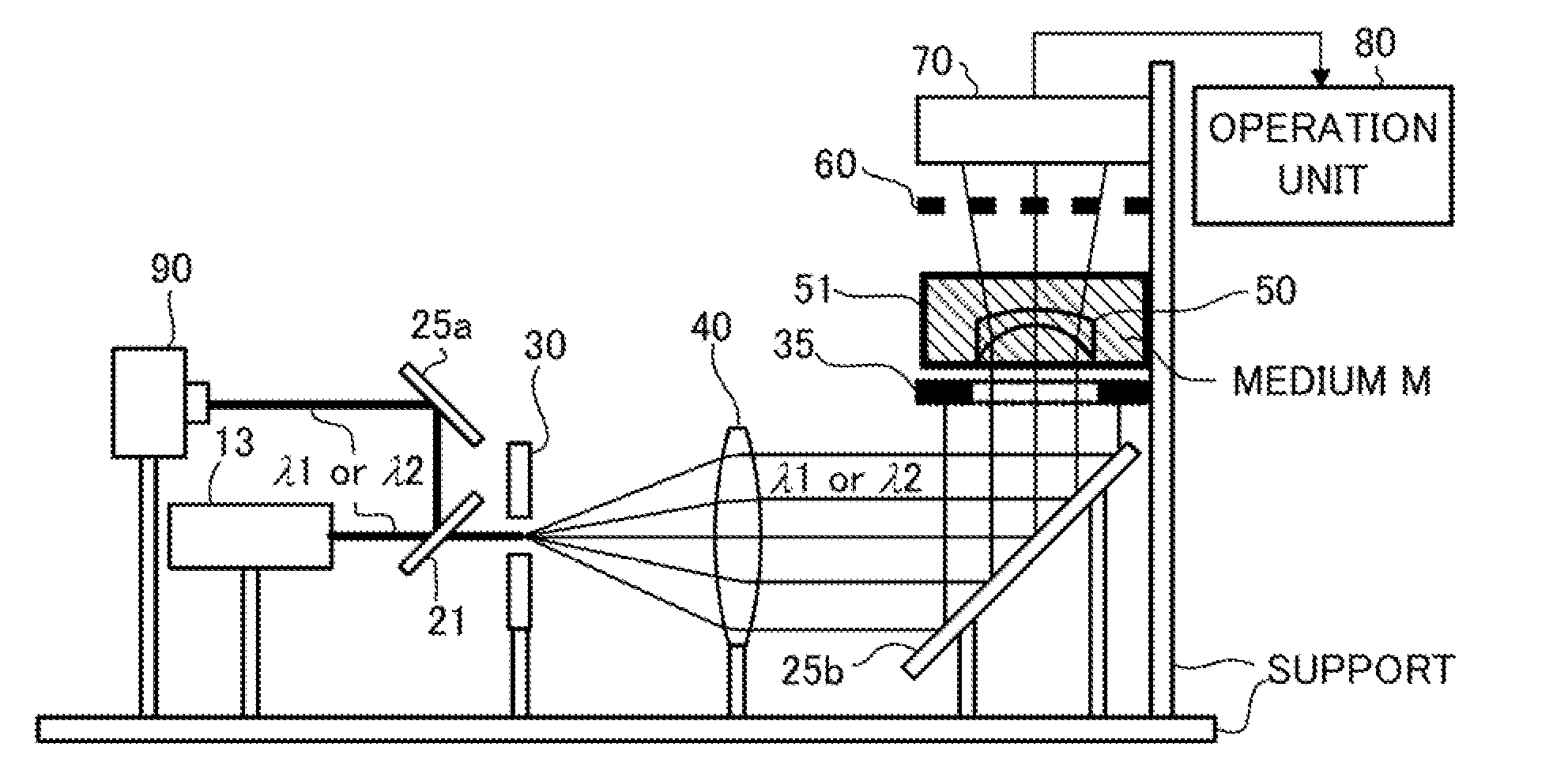
[0089]FIG. 5 is a block diagram of a measuring apparatus of this embodiment. The test object 50 is a lens (optical element) having a negative power. The medium M filled in a space around the test object 50 is, for example, oil. A light source 13 is a light source configured to emit beams of two or more wavelengths at proper timings, such as a wavelength variable laser (e.g., a semiconductor laser) or a combination of a broadband light source (e.g., a Halogen lamp) and a specific wavelength-selective filter. A Talbot interferometer is used to measure a transmitted wavefr...


PUM

PropertyMeasurementUnit
diameteraaaaaaaaaa
diameteraaaaaaaaaa
refractive index distributionaaaaaaaaaa

Abstract

A method includes measuring a transmitted wavefront of a test object by introducing reference light into the test object arranged in a medium having a refractive index different from a refractive index of the test object, and calculating a refractive index distribution of the test object by using a measurement result of the transmitted wavefront. The measuring step measures a first transmitted wavefront for a first wavelength and a second transmitted wavefront for a second wavelength different from the first wavelength. The calculating step calculates the refractive index distribution of the test object by removing a shape component of the test object utilizing measurement results of the first and the second transmitted wavefront, and a transmitted wavefront of a reference object arranged in the medium for each of the first and second wavelengths. The reference object has the same shape as the test object and a specific refractive index distribution.

Description

TECHNICAL FIELD[0001]The present invention relates to a refractive index distribution measuring method and a refractive index distribution measuring apparatus.BACKGROUND ART[0002]Japanese Patent Laid-Open No. (“JP”) 08-014852 proposes a method for finding a refractive index distribution of a flat-shaped test object using two beams having different wavelengths. JP 02-008726 proposes a method for finding a refractive index distribution of a test object by measuring a transmitted wavefront while the test object is immersed in each of two types of matching oils each having a slightly different refractive index from that of the test object.[0003]The method disclosed in JP 08-014852 requires working of the test object into the flat shape. The working of the test object is time-consuming, and changes the internal stress of the test object and thus its internal refractive index distribution before and after the working, thereby causing a refractive index distribution to be different from th...

Claims


Application Information

Patent Timeline
Patent Type & Authority Applications(United States)
IPC IPC(8): G01N21/41B29D11/00
CPCG01M11/0228G01N21/45G01M11/0271G01M11/0257G01M11/00G01M11/02
Inventor SUGIMOTO, TOMOHIRO
Owner CANON KK
Why Eureka
Try Eureka