Cutting apparatus and cutting control program therefor
- Summary
- Abstract
- Description
- Claims
- Application Information
AI Technical Summary
Benefits of technology
Problems solved by technology
Method used
Image

Examples
first embodiment
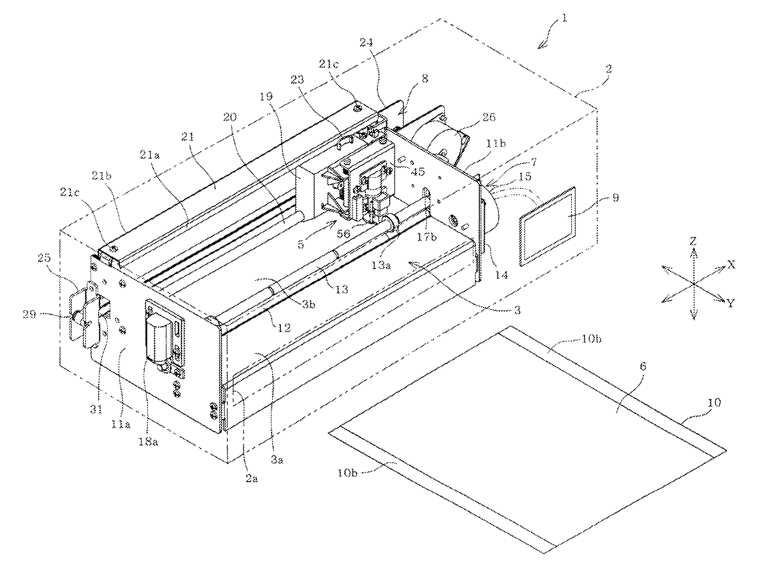
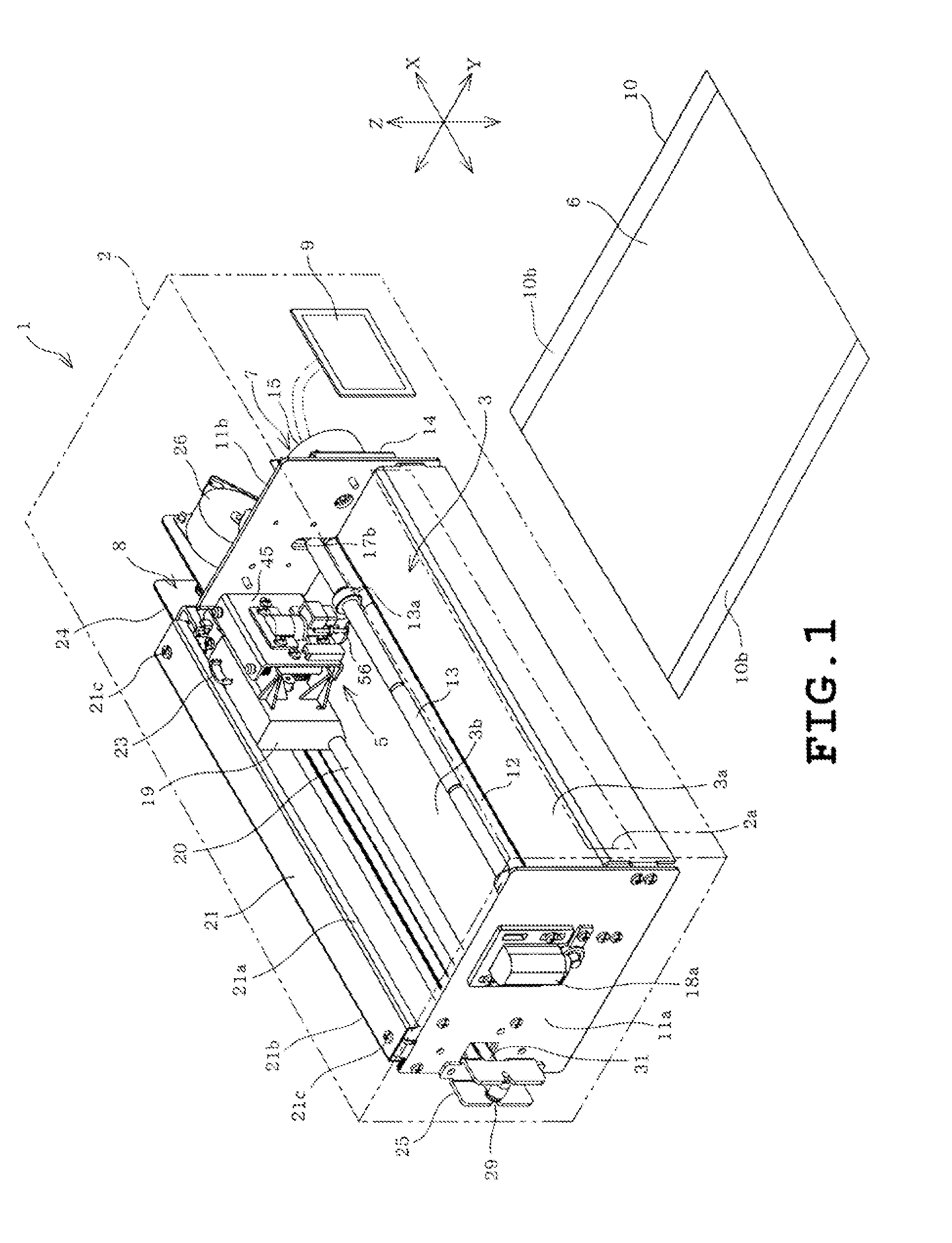
[0029]A first embodiment will be described with reference to FIGS. 1 to 11. Referring to FIG. 1, a cutting apparatus 1 includes a body cover 2 as a housing, a platen 3 provided in the body cover 2 and a cutter holder 5 also provided in the body cover 2. The cutting apparatus 1 also includes first and second moving units 7 and 8 for moving a cutter 4 (see FIG. 5) of the cutter holder 5 and an object 6 to be cut, relative to each other. The body cover 2 is formed into the shape of a horizontally long rectangular box and has a front formed with a horizontally long opening 2a which is provided for setting a holding sheet 10 holding the object 6. In the following description, the side where the user who operates the cutting apparatus 1 stands will be referred to as “front” and the opposite side will be referred to as “back.” The front-back direction thereof will be referred to as “Y direction.” The right-left direction perpendicular to the Y direction will be referred to as “X direction....
second embodiment
[0061]FIG. 12 illustrates a second embodiment. Only the difference between the first and second embodiments will be described. Identical or similar parts in the second embodiment are designated by the same reference symbols as those in the first embodiment. The cutter holder 5′ in the second embodiment differs from the cutter holder 5 of the first embodiment in the following. The solenoid 57, the mount 52e and the like are eliminated in the cutter holder 5′ and a compression coil spring 53 is disposed between the pressing member 56′ and the movable cylinder 46. The pressing member 56′ is held at a predetermined vertical position relative to the holder body 45. When the cutter holder 5′ occupies the lowered position as shown in FIG. 12, the contact portion 56f of the pressing member 56 presses the object 6 with the aforementioned pressing force FP. Thus, the pressing device 47′ is constituted by the pressing member 56′, the third moving unit 44, the control circuit 61, the compressio...
third embodiment
[0066]FIGS. 13A to 16 illustrate the third embodiment. Only the differences between the first and third embodiments will be described. The identical or similar parts in the third embodiment are labeled by the same reference symbols as those in the first embodiment.
[0067]Firstly, the cutting data includes line segment data corresponding to n number of line segments L1 to Ln composing the cutting line L. For example, when the pattern of a star is cut out of the object as shown in FIG. 13A, the cutting data has data of ten line segments comprising ten line segments L1 to Ln composing the cutting line L. More specifically, the line segments L1 to L10 have start points L1S to L10S and end points L1E to L10E respectively. The line segments L1 to L10 are continuous and constitute a closed single cutting line. Accordingly, start points of the line segments correspond with end points of the neighboring line segments respectively. The start and end points of the line segments L1 to L10 of the...
PUM
| Property | Measurement | Unit |
|---|---|---|
| Force | aaaaa | aaaaa |
| Angle | aaaaa | aaaaa |
| Adhesion strength | aaaaa | aaaaa |
Abstract
Description
Claims
Application Information
 - R&D
- Intellectual Property
- Life Sciences
- Materials
- Tech Scout
- Unparalleled Data Quality
- Higher Quality Content
- 60% Fewer Hallucinations
Browse by: Latest US Patents, China's latest patents, Technical Efficacy Thesaurus, Application Domain, Technology Topic, Popular Technical Reports.
© 2025 PatSnap. All rights reserved.Legal|Privacy policy|Modern Slavery Act Transparency Statement|Sitemap|About US| Contact US: help@patsnap.com