

Tubing Reel Assembly For Coiled Tubing Systems
- Summary
- Abstract
- Description
- Claims
- Application Information
AI Technical Summary
Benefits of technology
Problems solved by technology
Method used
Image

Examples
Embodiment Construction
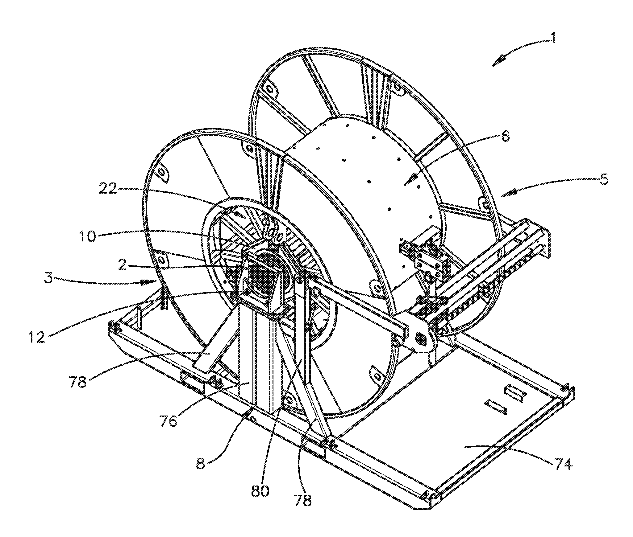
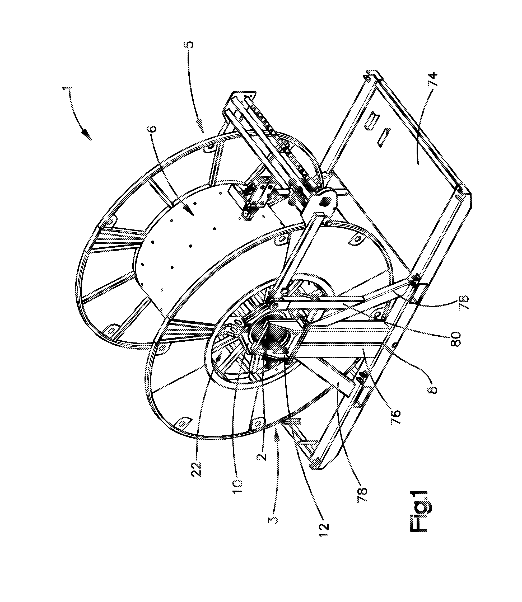
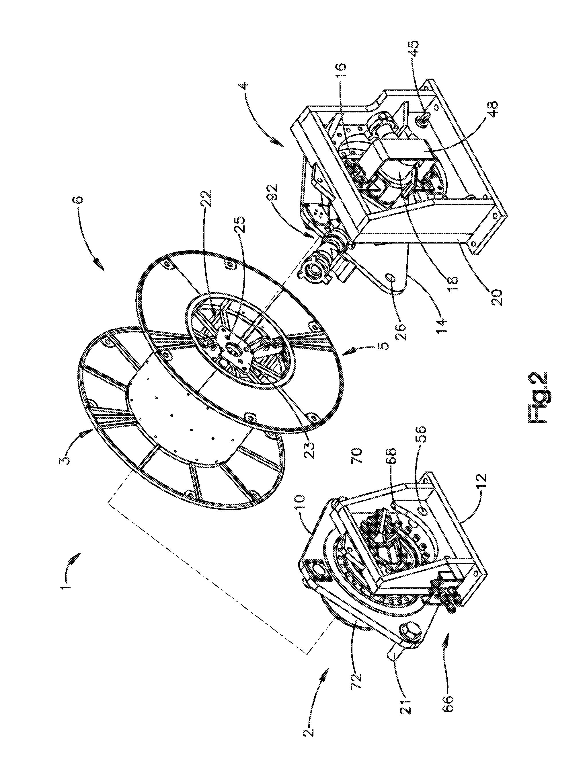
[0011]The embodiments of the present invention include a tubing reel assembly including a drive assembly, a swivel assembly, a reel, and a stand. The drive assembly includes a drive assembly adapter that connects the reel and the drive assembly, a drive assembly mount that connects the drive assembly and the stand, and a rotational power source. The swivel assembly includes a swivel assembly adapter that connects the reel and the swivel assembly, a swivel assembly mount that connects the swivel assembly and the stand, a bearing, and a hydraulic swivel. The reel includes recessed hubs that allow the overall width of the tubing reel assembly to be reduced, and the recessed hubs are used for connecting the drive assembly to the reel and the swivel assembly to the reel.
[0012]Another embodiment of the present invention is directed to a tubing reel assembly for coiled tubing systems including a drive assembly that includes a direct drive system, a drive assembly adapter, and a drive assem...
PUM
 Abstract
Description
Claims
Application Information