Imaging apparatus, image control method, and storage medium storing program

Active Publication Date: 2012-10-11
CASIO COMPUTER CO LTD
View PDF1 Cites 51 Cited by
  • Summary
  • Abstract
  • Description
  • Claims
  • Application Information

AI Technical Summary

Benefits of technology

[0010]Accordingly, it is an object of the present invention to provide an imaging apparatus, image control method, and storage medium storing program

Problems solved by technology

Accordingly, in an imaging environment in which an AC light source such as a fluorescent light or the like is used at the commercial power frequency of 60 Hz, the frame rate becomes an integral submultiple (½) of the commercial power frequency, and there has been a problem that linear noise is displayed as a flicker.
Further, when a high shutter speed is us

Method used


Image

  • Imaging apparatus, image control method, and storage medium storing program
  • Imaging apparatus, image control method, and storage medium storing program
  • Imaging apparatus, image control method, and storage medium storing program

Examples


Example

First Embodiment

[0030]Hereinafter, a first embodiment of a case where the present invention is applied to a digital camera will be described with reference to the drawings.

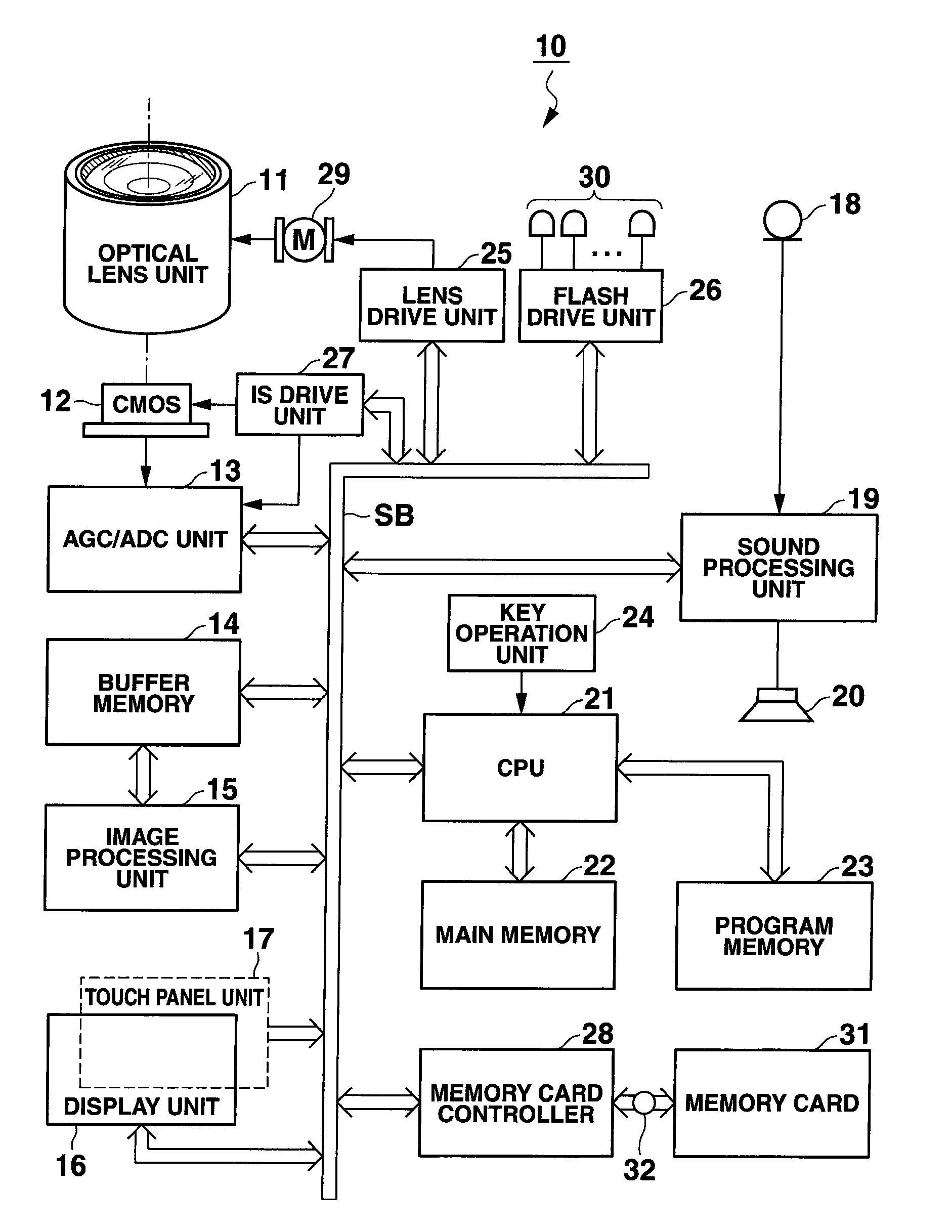
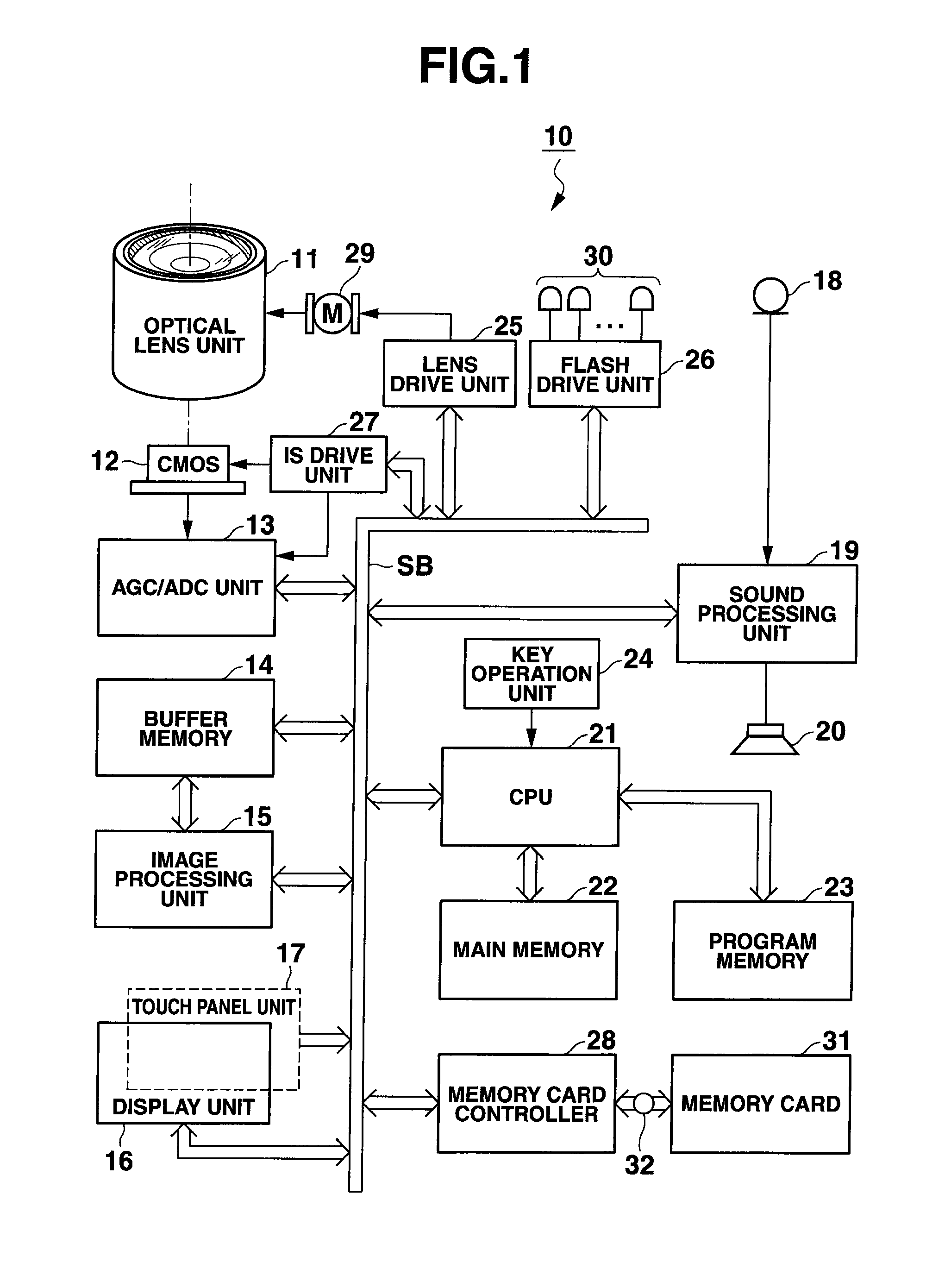
[0031]FIG. 1 is a view showing the circuit configuration of a digital camera 10 according to this embodiment.

[0032]In FIG. 1, a light figure of an object to be imaged is made incident on an imaging area of a solid-state imaging element, for example, a CMOS image sensor 12 through an optical lens unit 11 arranged on a front face of a camera body to thereby be formed thereon as an image.

[0033]In the live-view display state, an image signal obtained by the imaging of the CMOS image sensor 12 is subjected to correlated square sampling, automatic gain adjustment (AGC), and analog-to-digital conversion (ADC) in an AGC / ADC unit 13 to thereby be digitized. The image data of the digital value is sent to a buffer memory 14 through a system bus SB, and is held in the buffer memory 14.

[0034]An image processing unit 15 appropr...

Example

Second Embodiment

[0104]Hereinafter, a second embodiment of a case where the present invention is applied to a digital camera will be described with reference to the drawings.

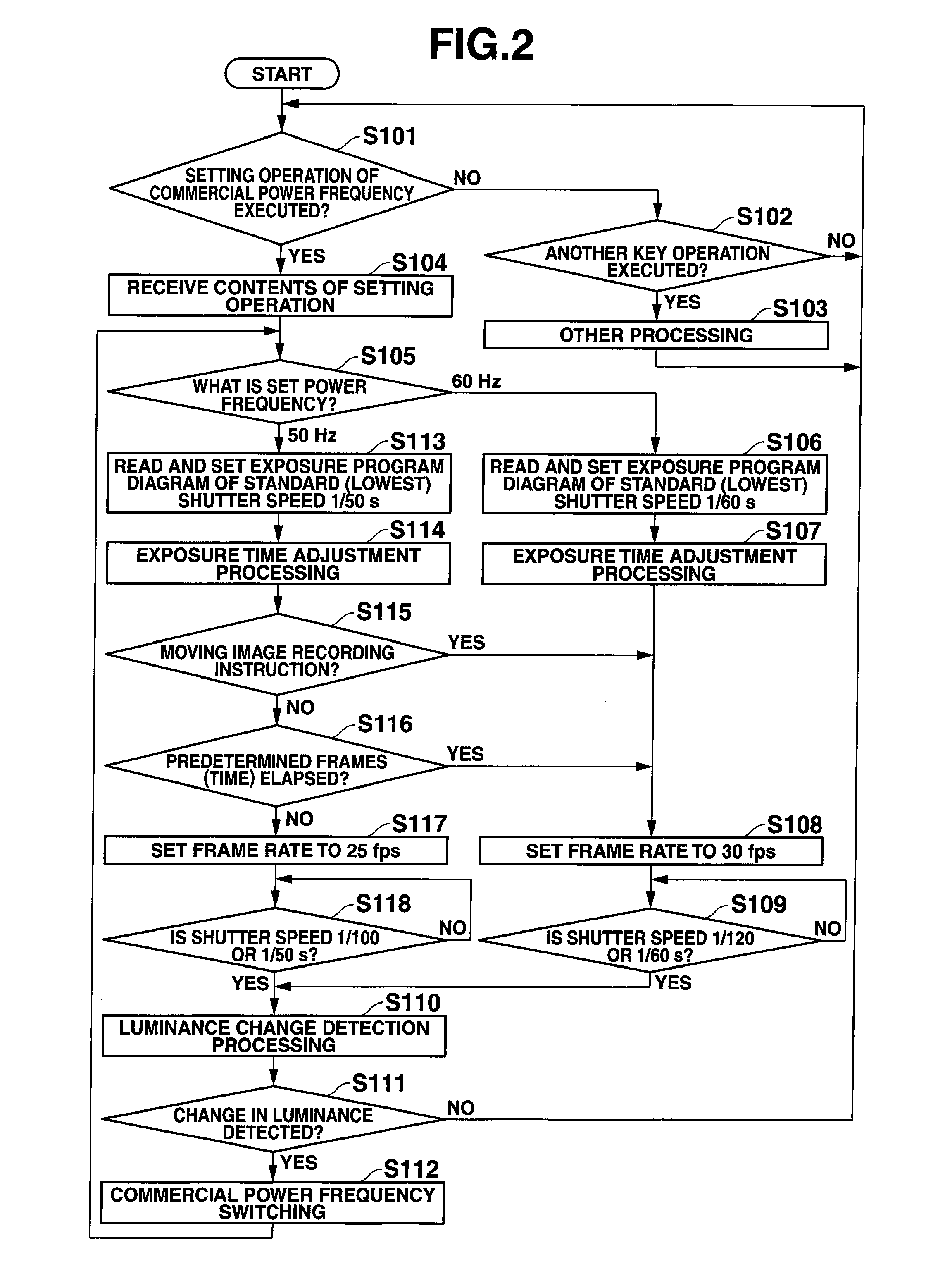
[0105]This second embodiment is contrived for the purpose of eliminating, to the utmost, an influence of a flicker due to imaging at a faster shutter speed than a normal shutter speed in a case where a higher shutter speed is used, such as a case of high dynamic range (HDR) image generation or the like in which a panoramic image is mainly generated by continuous-shooting synthesis or an image having a dynamic range enlarged by continuous-shooting synthesis is generated.

[0106]It should be noted that the circuit configuration of the digital camera itself according to this embodiment is basically identical to the digital camera 10 described in connection with FIG. 1, and hence identical parts are denoted by identical reference symbols, and their illustration and description will be omitted.

[0107]Further, in this em...


PUM


Abstract

A setting unit selects and sets one of a plurality of commercial power frequencies. A frame rate setting unit sets a frame rate corresponding to the commercial power frequency set by the setting unit. A control unit controls an imaging unit such that imaging is carried out at the frame rate set by the frame rate setting unit to thereby acquire image data successively. A detection unit detects a scanning line part at which luminance changes to differ between image data items successively acquired by the control unit. A changing unit changes the commercial power frequency set by the setting unit in accordance with a detection result obtained by the detection unit.

Description

CROSS-REFERENCE TO RELATED APPLICATIONS[0001]This application is based upon and claims the benefit of priority from prior Japanese Patent Application No. 2011-085422, filed Apr. 7, 2011, the entire contents of which are incorporated herein by reference.BACKGROUND OF THE INVENTION[0002]1. Field of the Invention[0003]The present invention relates, in particular, to an imaging apparatus, an image control method, and a storage medium storing program, capable of carrying out imaging in an illumination environment in which a light source driven by commercial power supply is used.[0004]2. Description of the Related Art[0005]As described in, for example, Jpn. Pat. Appln. KOKAI Publication No. 2009-152919, a technique of suppressing the occurrence of a flicker in a moving image to be recorded in an illumination environment in which a light source driven by commercial power supply is used is contrived.[0006]The occurrence of the flicker can be suppressed by coinciding a frequency at which the...

Claims


Application Information

Patent Timeline
IPC IPC(8): H04N5/235H04N9/68
CPCH04N5/2357H04N23/745
Inventor KATO, YOSHIYUKIMURAKAMI, TOMOHIKOKOMIYA, RIE
Owner CASIO COMPUTER CO LTD
Why Eureka
Try Eureka