
Image processing method for optical touch system

a technology of optical touch and image processing, applied in the field of image processing methods, can solve the problems of false signal generation, incorrect object coordinates may be computed, and the manor of light reflection may be changed,

Active Publication Date: 2012-10-18
PIXART IMAGING INC
View PDF4 Cites 13 Cited by
  • Summary
  • Abstract
  • Description
  • Claims
  • Application Information

AI Technical Summary

Benefits of technology

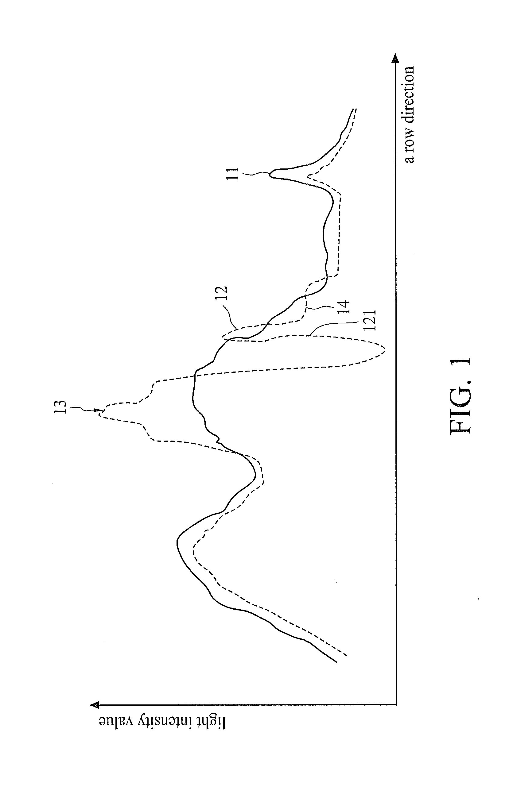
[0011]Yet another embodiment provides an image processing method for an optical touch system. The method comprises obtaining a background image and generating a background light distribution curve pattern representing the background image; obtaining an image and generating a light distribution curve pattern representing the image; determining a first target signal and a second target signal of the light distribution curve pattern in accordance with light intensity information of the light distribution curve pattern; computing first light intensity information of the first target signal and s...

Problems solved by technology

When an object touches the optical touch screen, the manner of light reflection may be changed such that a false signal is generated.
As a result, incorrect object coordinates may be computed, or the number of objects is incorrectly determined and real coordinates of the object are incorrectly calculated.

Method used


Image

  • Image processing method for optical touch system
  • Image processing method for optical touch system
  • Image processing method for optical touch system

Examples


Embodiment Construction

[0027]The following description is presented to enable any person skilled in the art to make and use the disclosed embodiments, and is provided in the context of a particular application and its requirements. Various modifications to the disclosed embodiments will be readily apparent to those skilled in the art, and the general principles defined herein may be applied to other embodiments and applications without departing from the spirit and scope of the disclosed embodiments. Thus, the disclosed embodiments are not limited to the embodiments shown, but are to be accorded the widest scope consistent with the principles and features disclosed herein.

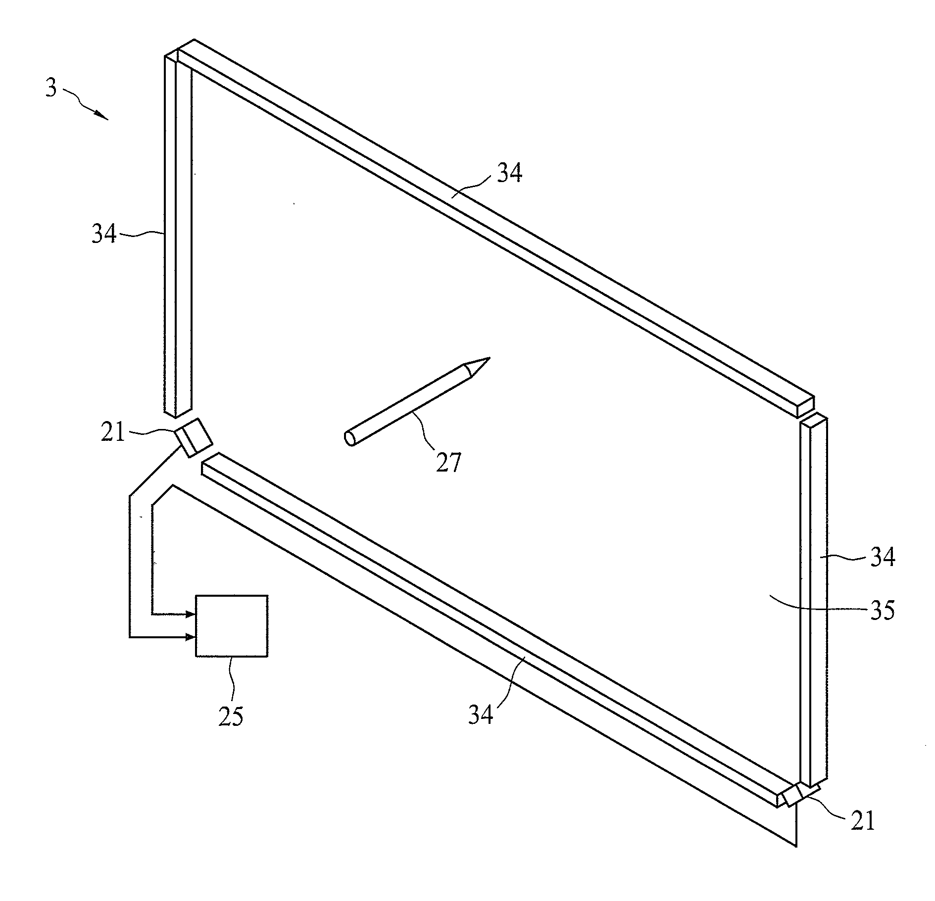
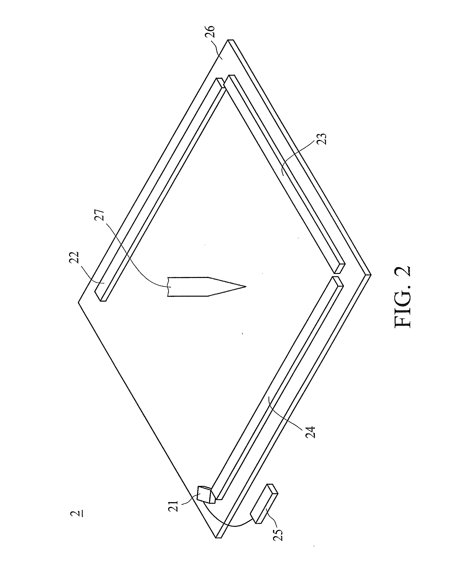
[0028]FIG. 2 schematically illustrates an optical touch system 2 according to one embodiment of the present invention. As shown in FIG. 2, the optical touch system 2 may comprise a sensor 21, a first light-providing member 22, a second light-providing member 23, a third light-providing member 24, and a processing unit 25. The first, seco...


PUM


Abstract

An image processing method for an optical touch system includes the steps of obtaining an image and generating a light distribution curve pattern from the image, selecting a target signal of the light distribution curve pattern in accordance with light intensity information of the light distribution curve pattern, determining at least one rising slope and at least one falling slope of the target signal, and selecting the target signal as an object signal when the absolute values of the at least one rising slope and at least one falling slope are greater than a threshold.

Description

CROSS-REFERENCE TO RELATED APPLICATION[0001]The present application is based on, and claims priority from, Taiwan Patent Application Serial Number 100112922, filed on Apr. 14, 2011, the disclosure of which is hereby incorporated by reference herein in its entirety.BACKGROUND[0002]1. Technical Field[0003]The present invention relates to an image processing method, and relates more particularly, but not exclusively, to an image processing method for an optical touch system.[0004]2. Related Art[0005]Touch screen devices are a type of electronic device that allows users to perform input operations directly on a screen. When a stylus, a finger tip or a similar object touches the screen, the touch screen device detects and calculates the position of the touch point, outputting coordinates to a computing system to allow the computing system to perform subsequent computing operations.[0006]Optical touch screens are a common type of developed touch screen devices. An optical touch screen usu...

Claims


Application Information

Patent Timeline
IPC IPC(8): G06F3/042
CPCG06F3/0421G06F3/0416
Inventor SU, TZUNG MINLIN, YU CHIAHSU, TENG WEILIN, CHIH HSINTSAI, CHENG NAN
Owner PIXART IMAGING INC
Learn More