Monitored ignition lock

a technology of ignition lock and monitoring device, applied in the direction of process and machine control, anti-theft devices, instruments, etc., can solve the problems of less than one drunk driving accident, inherently risky teen driving itself, and remains a national tragedy

Inactive Publication Date: 2012-10-25
IGEL PATRICIA J +1
View PDF14 Cites 90 Cited by
  • Summary
  • Abstract
  • Description
  • Claims
  • Application Information

AI Technical Summary

Benefits of technology

[0009]mom In accordance with the principles of the present invention, the teenage drinking and risky driving epidemic is addressed in a cost-effective manner. In accordance with the principles of the present invention, an effective, foolproof ignition interlock device is provided. A monitored ignition lock unit is contained within a vehicle. The monitored ignition lock unit is in communication with a weight sensor in the driver's seat (and optionally the passenger's seat), and seatbelt detection feature of the vehicle. A monitored ignition lock managing system is contained remotely from the vehicle. The monitored ignition lock unit and the monitored ignition lock managing system are in wireless communication. The monitored ignition lock unit includes a handheld device and a receiving station. The handheld device includes a substance detector, such as a blood alcohol conten

Problems solved by technology

Drunk driving remains a national tragedy.
However, that accounts for less than one percent of the 159 million self-reported episodes of alcohol-impaired driving among United States adults each year.
In addition, the statistics also bear out that due to lack of experience and responsibility, teen driving itself is inherently risky.
Crash risk is particularly high during the first year that teenagers are eligible to drive.
When a teenage driver's lack of experience and responsibility is combined with drinking and driving, a lethal combination results.
While devices exist that a

Method used


Image

  • Monitored ignition lock
  • Monitored ignition lock
  • Monitored ignition lock

Examples


Embodiment Construction

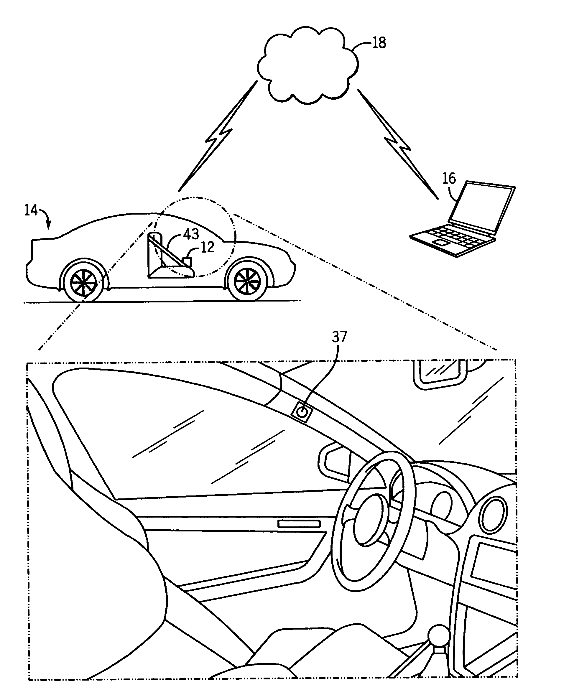
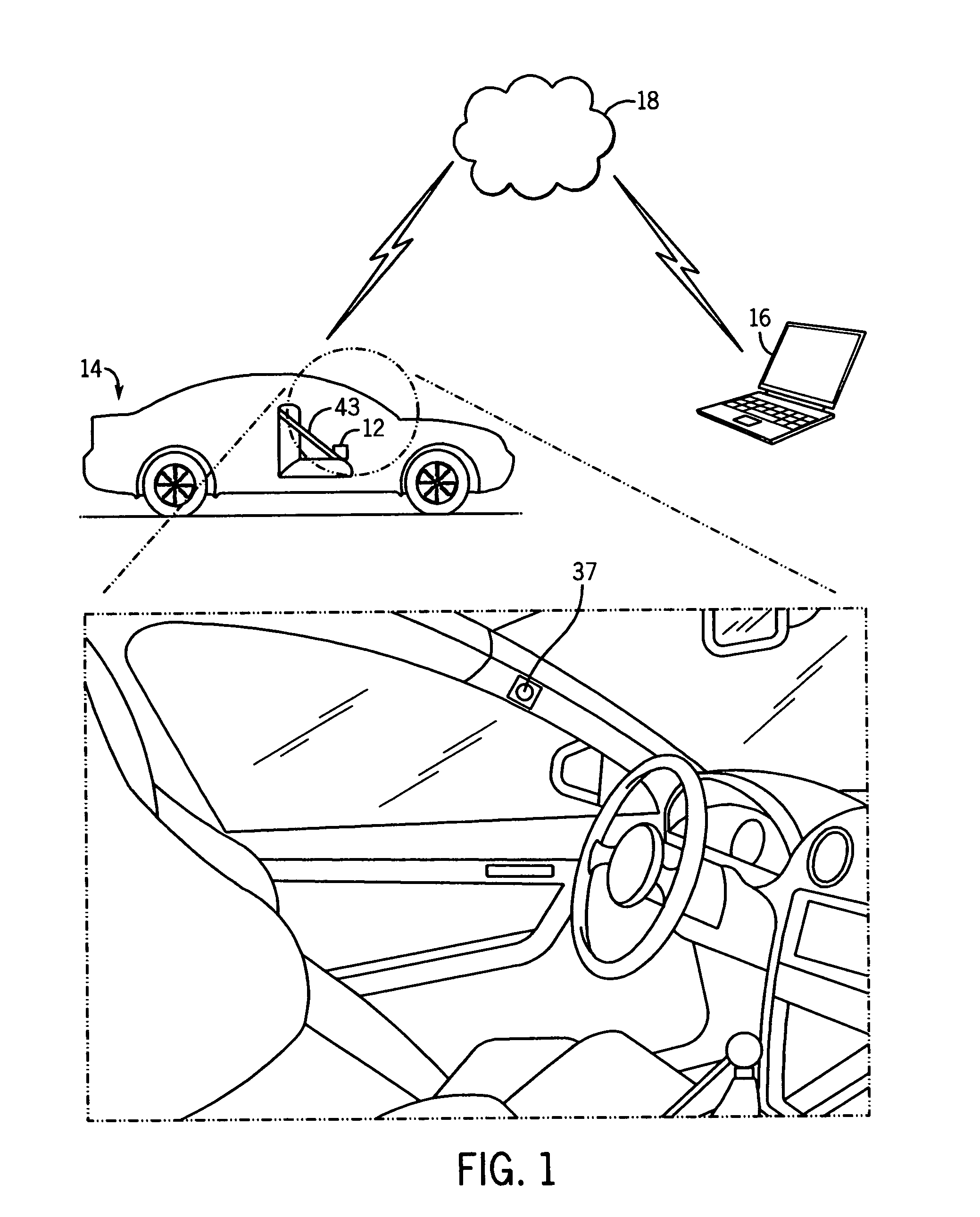
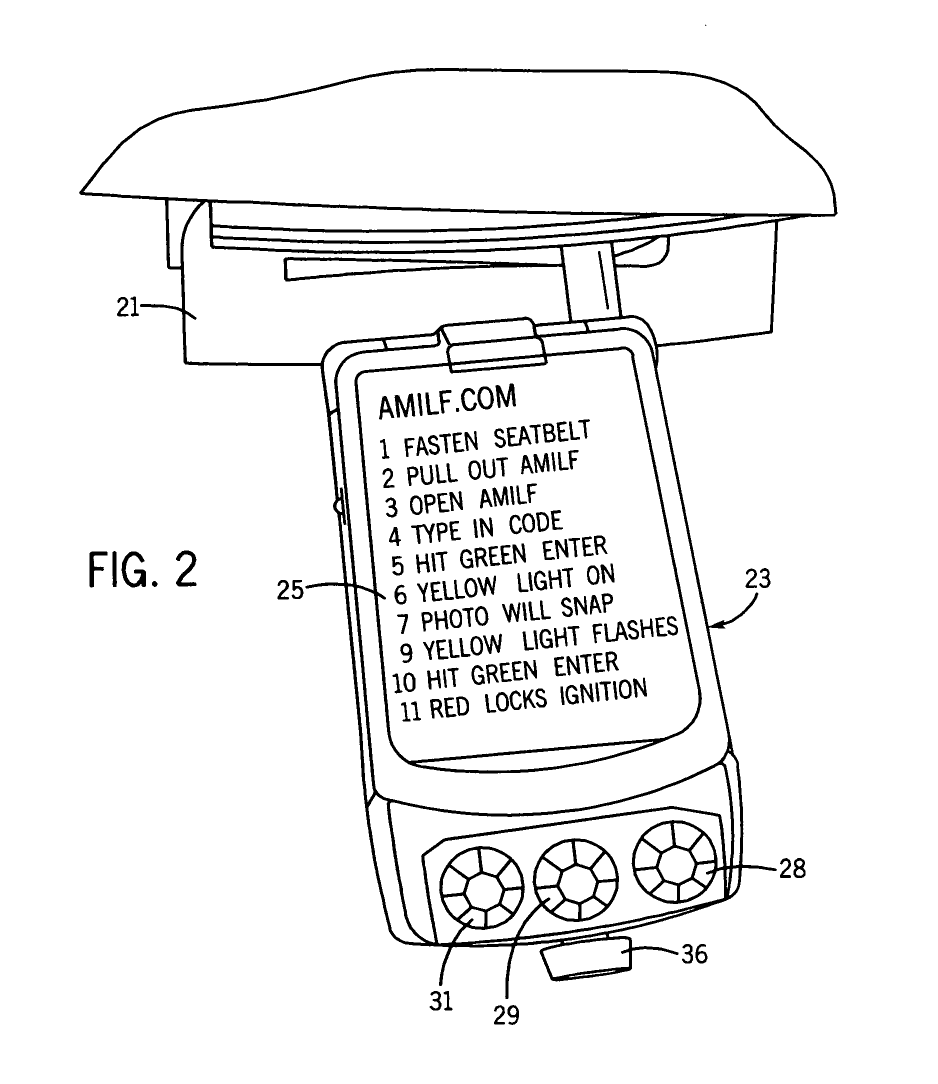
[0014]In accordance with the principles of the present invention, a monitored ignition lock system is provided. A monitored ignition lock system in accordance with the principles of the present invention stops a vehicle from starting to preclude a driver who has exceeded a predetermined level of a substance such as alcohol in his or her system from driving. A monitored ignition lock in accordance with the principles of the present invention confirms a user's identity. A monitored ignition lock in accordance with the principles of the present invention confirms that a safety belt is connected when a user is sitting is the drivers seat (or optionally a passenger in the passenger's seat) of the vehicle. A monitored ignition lock in accordance with the principles of the present invention provides for remote monitoring of the vehicle. A monitored ignition lock in accordance with the principles of the present invention can optionally prevent use of a cellular phone, both in voice and text...


PUM


Abstract

A monitored ignition system is provided. A monitored ignition lock unit is contained within a vehicle. The monitored ignition lock unit is in communication with a weight sensor in the driver's seat and a seatbelt detection feature of the vehicle. A monitored ignition lock managing system is contained remotely from the vehicle. The monitored ignition lock and the unit monitored ignition lock managing system are in wireless communication. The monitored ignition lock unit includes a handheld device and a receiving station. The handheld device includes a substance detector, such as a breathalyzer. A camera is aimed to photograph a user when engaged with the substance detector. The handheld device and the receiving station are connected via a tether. The tether is sized such that only a driver sitting relatively close to the monitored ignition lock unit docking can access the substance detector provided in the monitored ignition lock handheld device. If the user exceeds a predetermined reading from the substance detector, the vehicle is stopped from starting. Whether engine starting is allowed or disallowed, a message can be sent to the monitored ignition lock managing system.

Description

FIELD OF THE INVENTION[0001]The present invention relates to automobile safety.BACKGROUND OF THE INVENTION[0002]Drunk driving remains a national tragedy. In 2009, over 1.4 million drivers were arrested for driving under the influence of alcohol or narcotics. (Department of Justice (US), Federal Bureau of Investigation (FBI). “Crime in the United States 2009: Uniform Crime Reports”. Washington, DC (2010)). However, that accounts for less than one percent of the 159 million self-reported episodes of alcohol-impaired driving among United States adults each year. (Quinlan, K P; Brewer, R D; Siegel, P; Sleet, D A; Mokdad, A H; Shults, R A; Flowers, N. “Alcohol-impaired driving among U.S. adults, 1993-2002”. 28(4) American Journal of Preventive Medicine 346 (2005)).[0003]In 2009, 10,839 people were killed in alcohol-impaired driving crashes, accounting for nearly one-third (32%) of all traffic-related deaths in the United States. (Dept of Transportation (US), National Highway Traffic Safe...

Claims


Application Information

Patent Timeline
IPC IPC(8): B60R25/00B60R25/10
CPCB60R25/00
Inventor IGEL, PATRICIA J.IGEL, JEFFREY M.
Owner IGEL PATRICIA J
Why Eureka
Try Eureka