Environment recognition device and environment recognition method

a recognition device and environment technology, applied in scene recognition, instruments, computing, etc., can solve the problems of reducing taking a vast amount of processing time to complete the entire image processing, etc., to improve the efficiency and accuracy of specifying target objects, the effect of reducing processing tim

Inactive Publication Date: 2012-10-25
SUBARU CORP
View PDF4 Cites 38 Cited by
  • Summary
  • Abstract
  • Description
  • Claims
  • Application Information

AI Technical Summary

Benefits of technology

[0009]In view of such problems, it is an object of the present invention to provide an environment recognition device and an environment recognition method that improve the efficiency and accuracy of specifying a target object and that reduce the processing time.
[0014]The data retaining unit may further retain a range of size in association with the specific object, and the specific object determining unit may determine that the target object is the specific object according to the size of the target object on the basis of the association retained in the data retaining unit.
[0017]According to the present invention, a target object is specified by a plurality of parameters such as luminance and height, and therefore, the efficiency and accuracy of specifying the target object can be improved, and the processing time can be reduced.

Problems solved by technology

This takes a vast amount of processing time to complete the processing of the entire image.
Moreover, in some cases, pixels unnecessary for the control are grouped uselessly, thereby reducing the efficiency and accuracy of specifying the target object.

Method used


Image

  • Environment recognition device and environment recognition method
  • Environment recognition device and environment recognition method
  • Environment recognition device and environment recognition method

Examples


Embodiment Construction

[0029]A preferred embodiment of the present invention will be hereinafter explained in detail with reference to attached drawings. The size, materials, and other specific numerical values shown in the embodiment are merely exemplification for the sake of easy understanding of the invention, and unless otherwise specified, they do not limit the present invention. In the specification and the drawings, elements having substantially same functions and configurations are denoted with same reference numerals, and repeated explanation thereabout is omitted. Elements not directly related to the present invention are omitted in the drawings.

(Environment Recognition System 100)

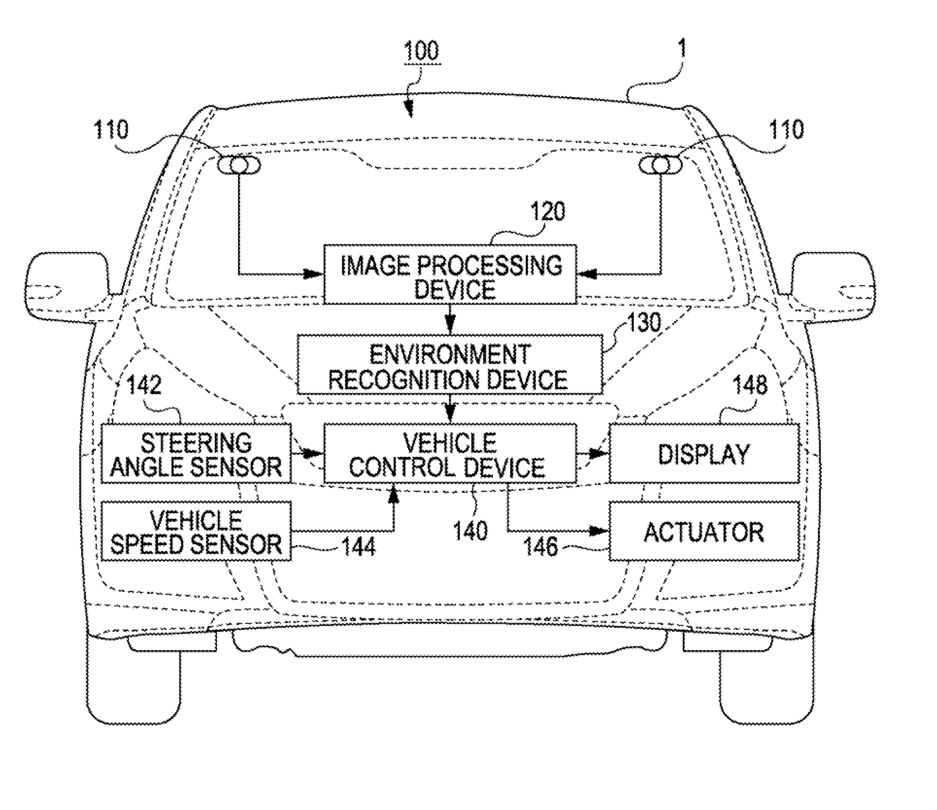
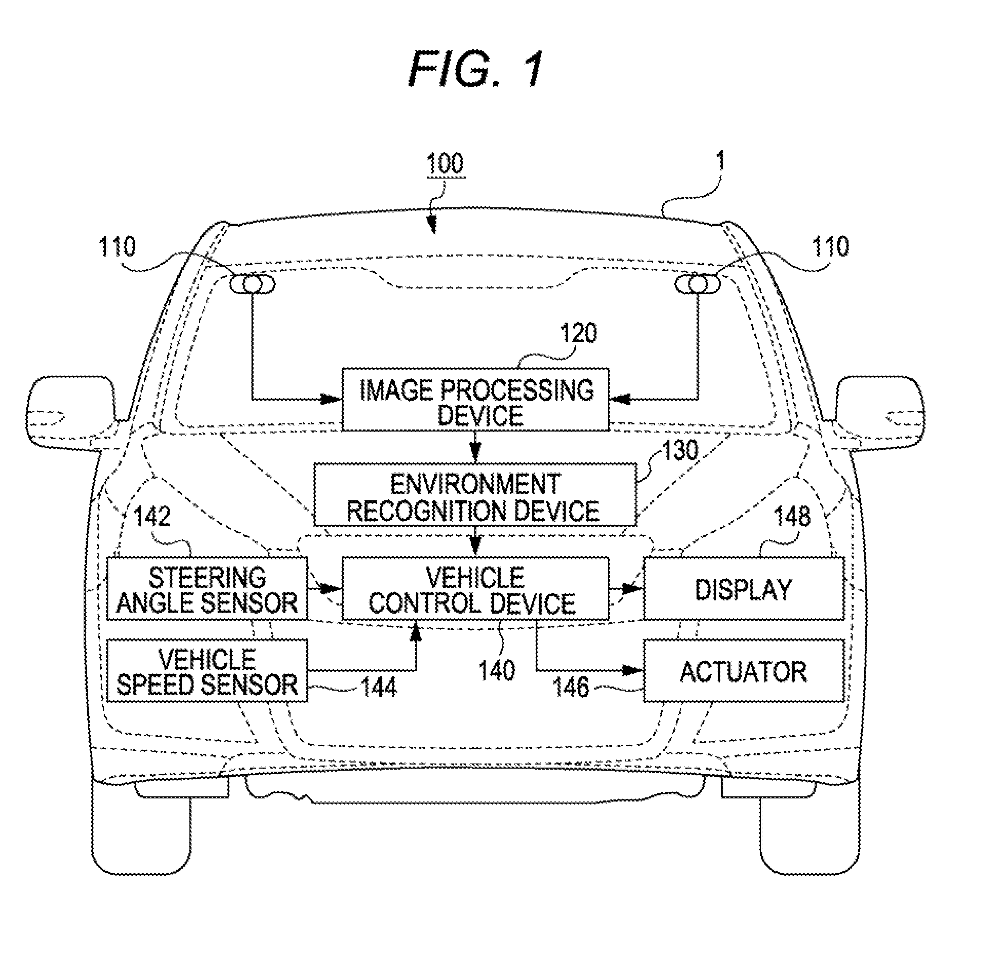
[0030]FIG. 1 is a block diagram illustrating connection relationship in an environment recognition system 100. The environment recognition system 100 includes a plurality of image capturing devices 110 (two image capturing devices 110 in the present embodiment), an image processing device 120, an environment recognitio...


PUM


Abstract

An environment recognition device obtains a luminance of a target portion existing in a detection area, obtains a height of the target portion, and provisionally determines a specific object corresponding to the target portion or determines a specific object corresponding to grouped target objects, according to the luminance and the height of the target portion based on the association (specific object table) of a range of luminance and a range of height from a road surface with the specific object which is retained in a data retaining unit.

Description

CROSS-REFERENCE TO RELATED APPLICATIONS[0001]The present application claims priority from Japanese Patent Application No. 2011-096067 filed on Apr. 22, 2011, the entire contents of which are hereby incorporated by reference.BACKGROUND OF THE INVENTION[0002]1. Field of the Invention[0003]The present invention relates to an environment recognition device and an environment recognition method for recognizing a target object based on luminances of the target object in a detection area.[0004]2. Description of Related Art[0005]Conventionally, a technique has been known that detects a target object such as an obstacle including a vehicle and a traffic light located in front of a subject vehicle for performing control to avoid collision with the detected target object and to maintain a safe distance between the subject vehicle and the preceding vehicle (for example, Japanese Patent No. 3349060 (Japanese Patent Application Laid-Open (JP-A) No. 10-283461).[0006]Further, in such techniques, th...

Claims


Application Information

Patent Timeline
Patent Type & Authority Applications(United States)
IPC IPC(8): G06K9/00
CPCG08G1/165G06K9/00825G06K9/00805G08G1/166G06V20/58G06V20/584
Inventor SAITO, TORU
Owner SUBARU CORP
Why Eureka
Try Eureka