
Mounting-error inspecting method and substrate inspecting apparatus using the method

a technology of mounting error and inspection method, which is applied in the direction of material analysis, optically investigating flaws/contamination, instruments, etc., can solve the problems of component mounting error, mounting error may occur in the component to be replenished or replaced, etc., to improve the efficiency and accuracy of inspection.

Inactive Publication Date: 2008-04-08
OMRAON
View PDF14 Cites 21 Cited by
  • Summary
  • Abstract
  • Description
  • Claims
  • Application Information

AI Technical Summary

Benefits of technology

"The present invention improves the efficiency and accuracy of inspecting components by restricting the mounting error inspection to only the components that are actually being replaced or replenished in a component mounting step. This is done by setting component identifying information and substrate identifying information in the component mounting step and specifying the substrate on which the component is mounted. By doing so, it is possible to inspect a large number of components without having to individually enter information for comparison. The invention also reduces the number of disinformation by allowing the inspection to be performed on the basis of the identifying information of the substrate and components. This method improves the efficiency of mounting error inspection and reduces the number of pieces of disinformation."

Problems solved by technology

As described above, a component mounting error occurs due to a human error in a component mounting step.
Therefore, when a component is replenished or replaced due to the change of a substrate to be fabricated in the component mounting step, a mounting error may occur in the component to be replenished or replaced.

Method used


Image

  • Mounting-error inspecting method and substrate inspecting apparatus using the method
  • Mounting-error inspecting method and substrate inspecting apparatus using the method
  • Mounting-error inspecting method and substrate inspecting apparatus using the method

Examples


Embodiment Construction

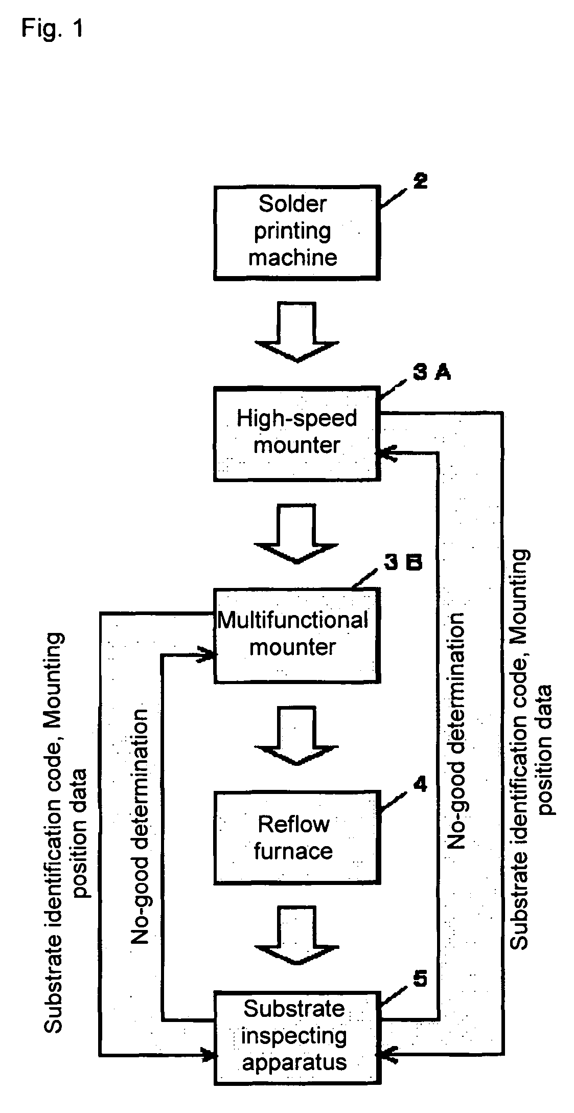
[0073]FIG. 1 shows a flow (thick arrow) of a substrate and a flow (thin arrow) of information exchanged between devices for mounting error inspection on a substrate fabricating line applied with mounting error inspection of the present invention.

[0074]The illustrated substrate fabricating line includes a solder printing machine 2, high-speed mounter 3A, multifunctional mounter 3B, reflow furnace 4, and substrate inspecting apparatus 5. A substrate carrying conveyer (not illustrated) is set between the above installations and substrates are successively sent to each installation to undergo processing.

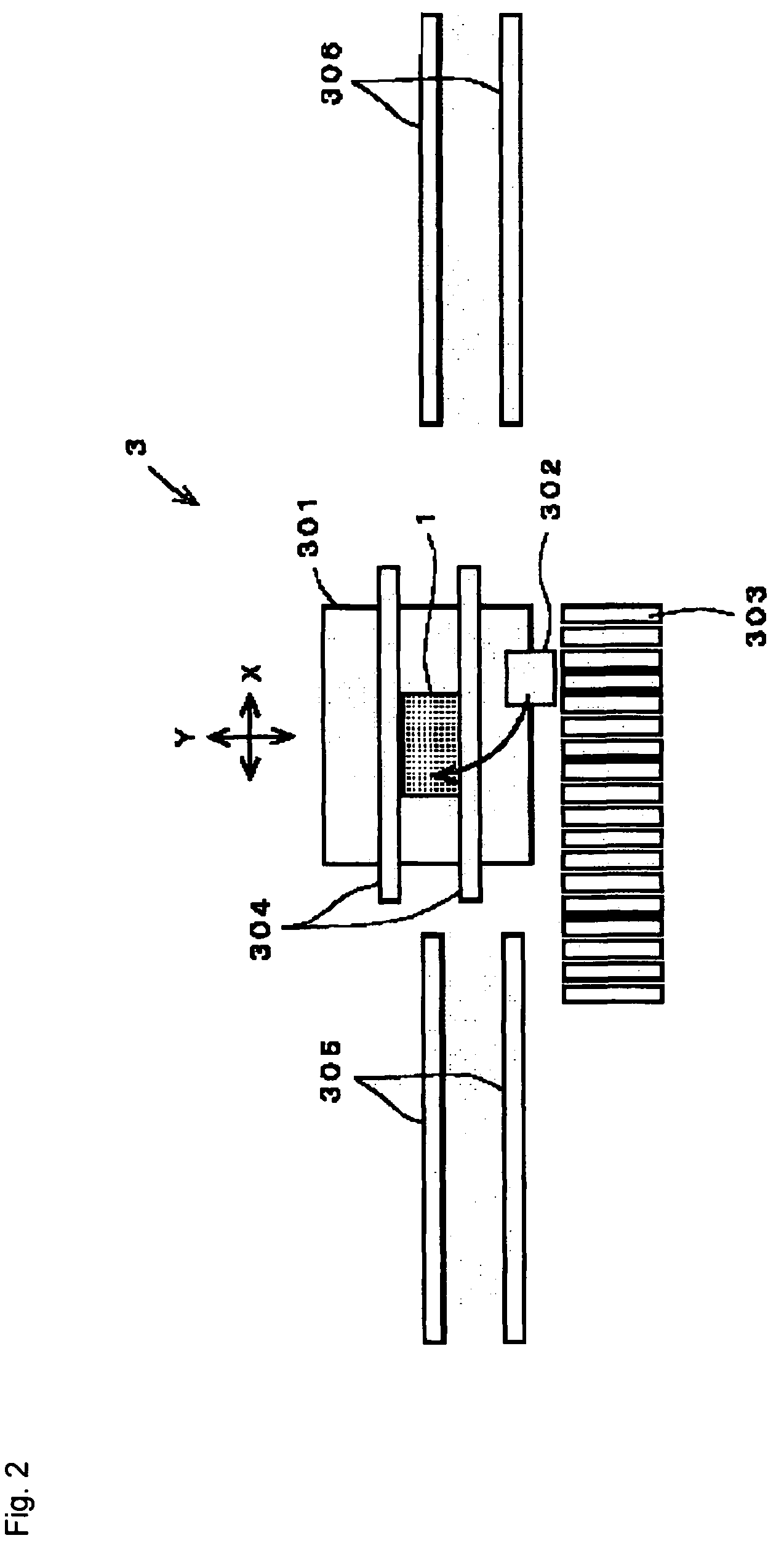
[0075]The solder printing machine 2 receives a printed circuit board and applies cream solder to the soldering position of each component. The high-speed mounter 3A is a device for mounting a chip component at a high speed and the multifunctional mounter 3B is used to mount components other than a chip component. The reflow furnace 4 heats a substrate passing through a component mounting...


PUM

PropertyMeasurementUnit
densityaaaaaaaaaa
heightaaaaaaaaaa
timeaaaaaaaaaa

Abstract

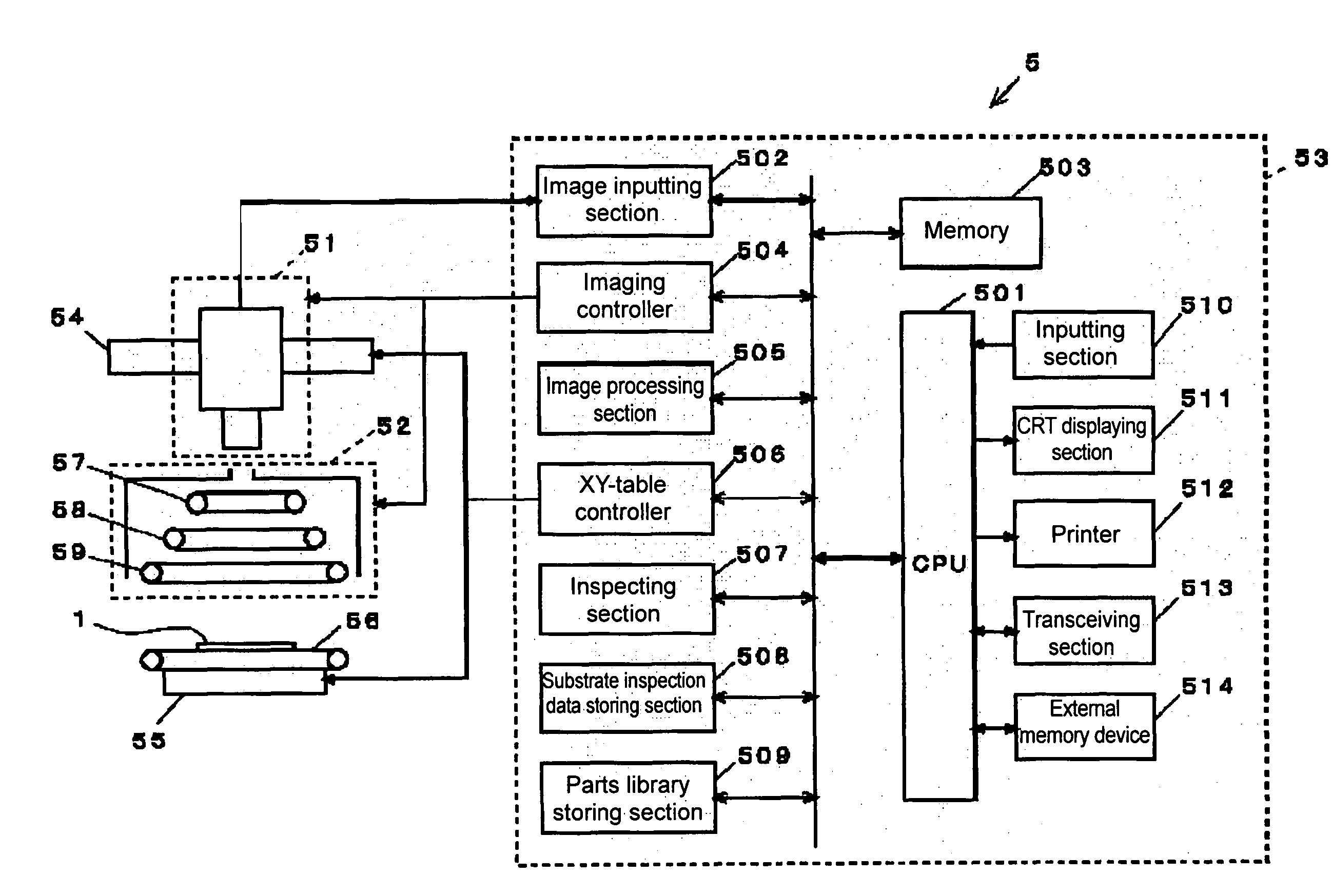
When a component is replaced or replenished in a predetermined feeder, mounters 3A and 3B refer to mount data in accordance with the feeder number for the feeder and read out the mounting position of the replaced or replenished component. The mounting position data is transmitted to a substrate inspecting apparatus 5 together with the substrate identification code of a substrate first processed after reel replacement. When the substrate corresponding to the substrate identification code is supplied, the substrate inspecting apparatus 5 refers to substrate inspection data in accordance with the mounting position data, specifies a component to be inspected, and executes the mounting error inspection according to character-string recognition for the specified component. When a mounting error is detected in this inspection, the substrate inspecting apparatus 5 transmits no-good determination to the mounters 3A and 3B receiving information.

Description

BACKGROUND OF THE INVENTION[0001]1. Field of the Invention[0002]The present invention belongs to a technical field for inspecting a printed circuit board (hereafter referred to as “component mounting substrate” or simply referred to as “substrate”) with components mounted. Particularly, the present invention relates to a method for performing inspection on whether a correct component is mounted on a substrate to be inspected and an apparatus having a function of executing the inspecting method.[0003]2. Description of Prior Art[0004]A component mounting machine referred to as “mounter” has been used so far in order to automate high-density component mounting. A plurality of component supplying devices respectively referred to as “feeder” is set on the mounter. Each feeder holds many same types of components and is managed in accordance with a specific identification number referred to as “feeder number”.[0005]Data showing that the component of which feeder is mounted on which substra...

Claims


Application Information

Patent Timeline
Patent Type & Authority Patents(United States)
IPC IPC(8): G06K9/00G01N21/88H01L21/00H05K13/08
CPCG01N21/8851H01L21/67253H01L21/67294H05K13/08H05K13/084H05K13/0815
Inventor FUJII, YOSHIKIYAMAZAKI, HIROSHI
Owner OMRAON
Learn More