Automated test method

a test method and automatic technology, applied in the direction of resistance/reactance/impedence, testing circuit, instruments, etc., can solve the problems of creating safety doubts for users, defects and inaccuracy in the entire test process, and the manual way of conducting the test cannot meet the precise and accurate requirements needed. , to achieve the effect of improving production yield, quality and safe operation of fabricated electrical devices, and accurate and efficient manner

Inactive Publication Date: 2006-03-28
INVENTEC CORP
View PDF16 Cites 24 Cited by
  • Summary
  • Abstract
  • Description
  • Claims
  • Application Information

AI Technical Summary

Benefits of technology

[0009]Therefore, the automated test method according to the invention can automatically carry out a hi-pot test for an electrical device to be tested in an accurate and efficient manner. This thereby eliminates the prior-art drawbacks caused by manual operation of the hi-pot test, for example, inefficient and inaccurate test performance under human control, etc. Since the hi-pot test performed by the automated test method would be thoroughly conducted for each electrical device, such that test faults, such as missed inspection and wrong inspection caused by human error, can be prevented, thereby ensuring quality and safe operation of the fabricated electrical devices. In the absence of human errors, each electrical device can be accurately and precisely tested, thereby improving the production yield and saving costs to remedy the human errors.

Problems solved by technology

If the electrical device is not subject to a complete hi-pot test procedure, it creates safety doubt for the user.
Hi-pot testing is a highly repetitive and mind-numbing task that easily fatigues the operators and creates uncertainties, which would result in defects and inaccuracies in the entire test process.
In many respects, the manual way of conducting the test can no longer satisfy the precise and accurate requirements needed to ensure quality of the current electrical products which are usually assembled by complex interconnection of a variety of electrical modules into compact electrical devices of high reliability.

Method used


Image

  • Automated test method
  • Automated test method
  • Automated test method

Examples


Embodiment Construction

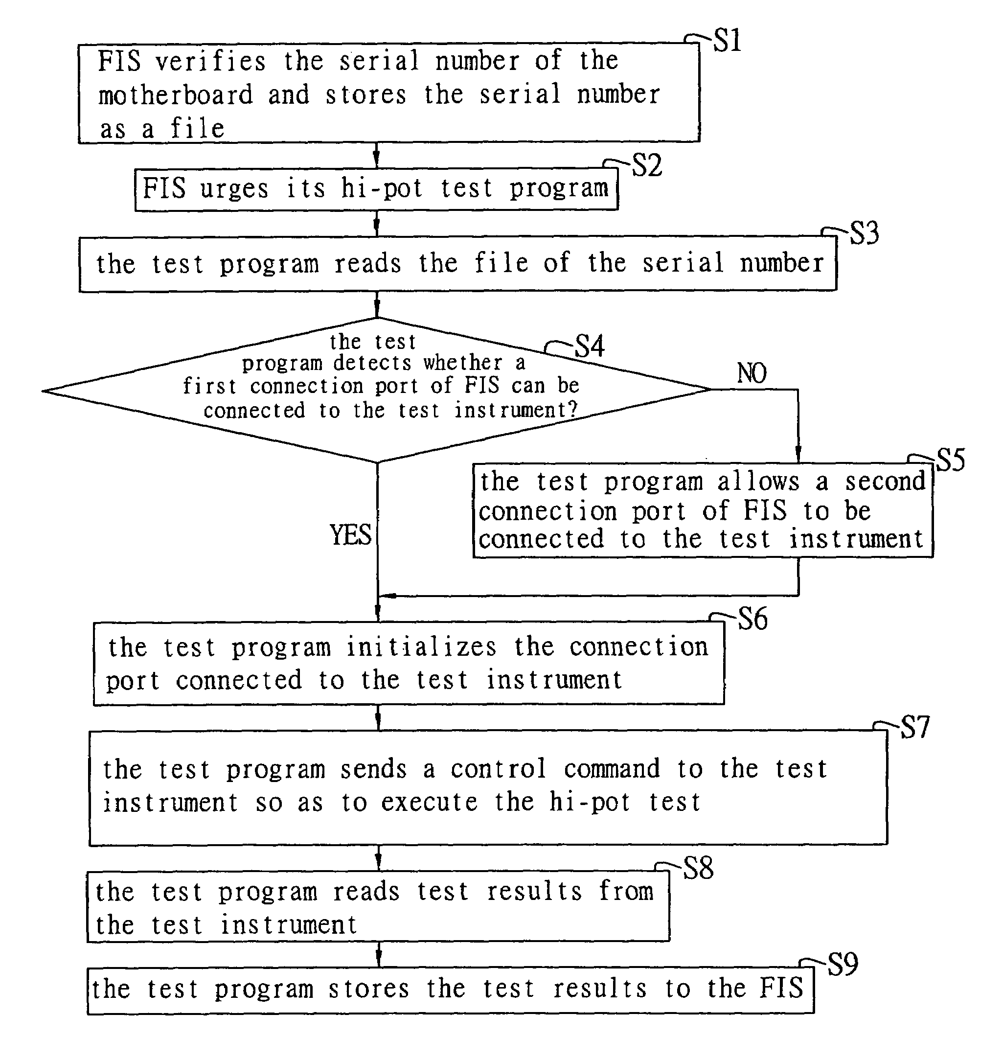
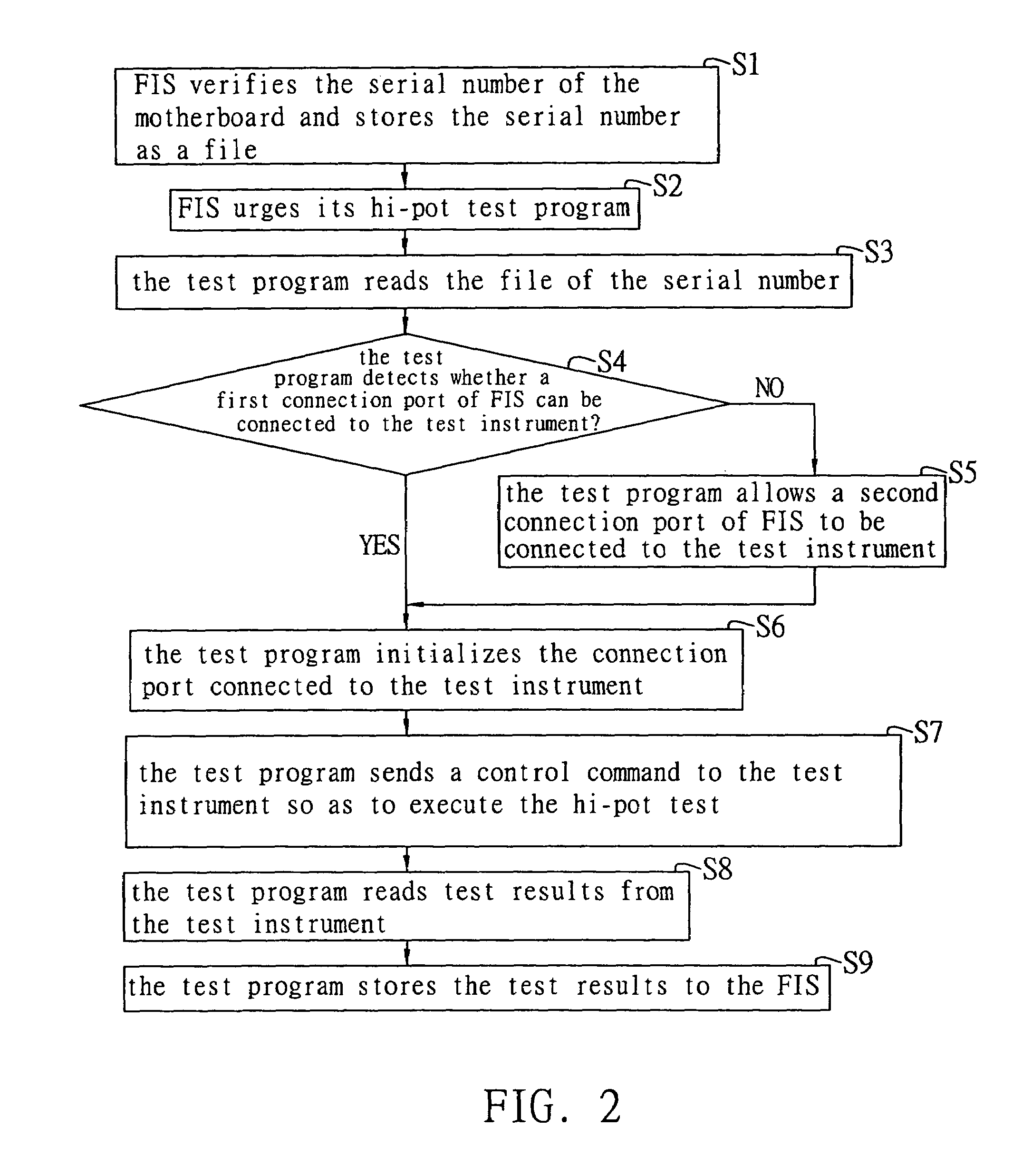
[0014]The following preferred embodiment in detail describes the use of an automated test method according to the present invention to automatically test voltage tolerance or perform a hi-pot test for an electrical device such as, but not limited to, motherboard, in an accurate and efficient manner.

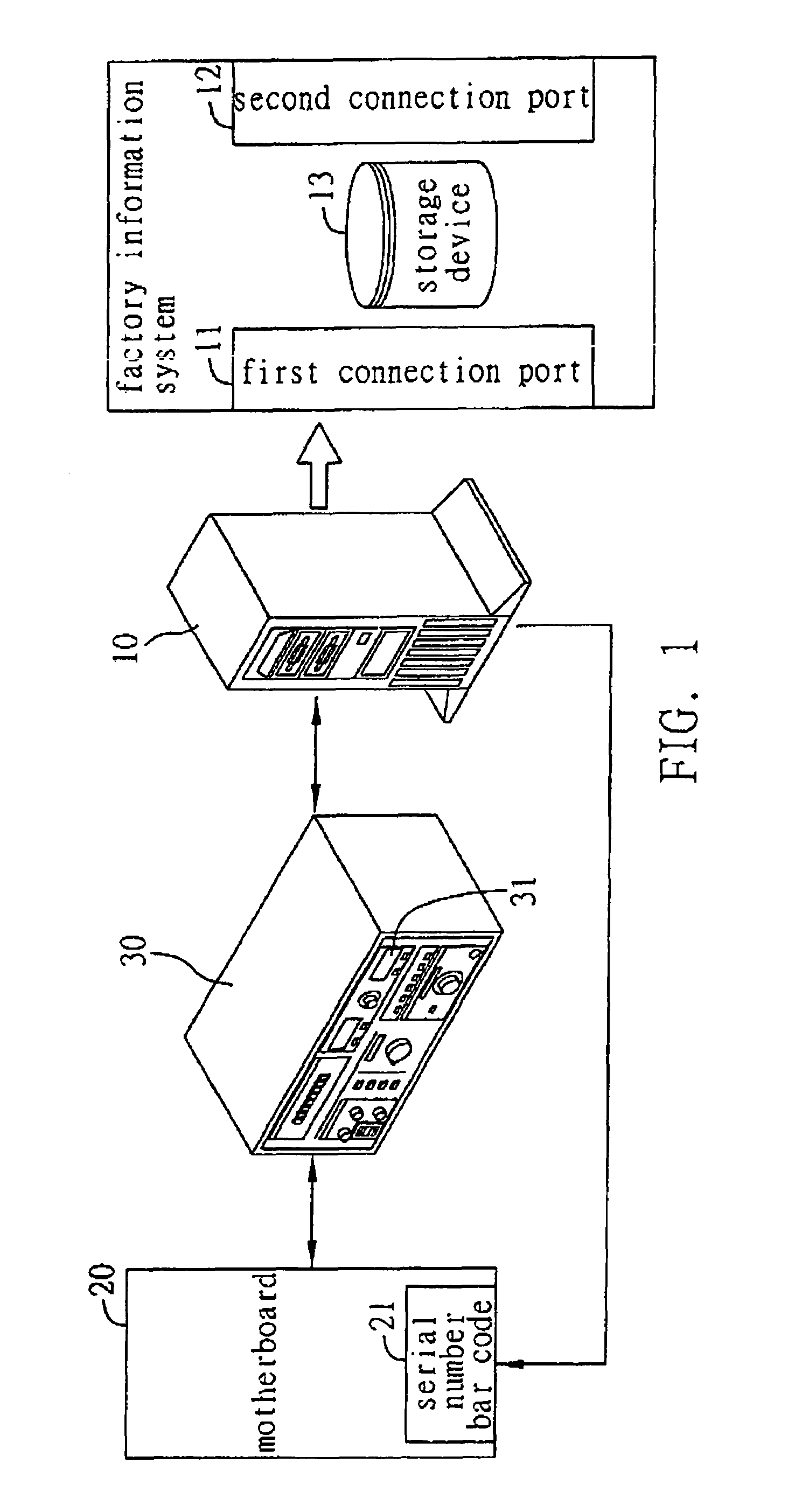
[0015]FIG. 1 illustrates operating architecture for performing the hi-pot test for the motherboard 20 using the automated test method according to the invention. The operating architecture includes an operating system such as Factory Information System (FIS) 10, a hi-pot test instrument 30, and the motherboard 20. The FIS 10 reads a serial number bar code 21 on the motherboard 20, and stores the serial number of the motherboard 20 as a file in a predetermined folder of a storage device 13 of the FIS 10 once the serial number is verified being correct. A hi-pot test program installed in the FIS 10 is urged to read the file of the serial number and to initialize a first connection port 11 (...


PUM


Abstract

An automated test method for performing a hi-pot test procedure for an electrical device through the use of a test program installed in a factory information system (FIS) and a test instrument connected to the FIS. The test program sends a control command to the test instrument that in turn executes the hi-pot test for the electrical device. Test results are obtained by the test program from the test instrument and sent to the FIS. The test results are stored in the FIS for future reference.

Description

[0001]This nonprovisional application claims priority under 35 U.S.C. § 119(a) on Patent Application No(s). 092105069 filed in Taiwan, R.O.C. on Mar. 10, 2003, the entire contents of which are hereby incorporated by reference.FIELD OF THE INVENTION[0002]The present invention relates to methods for testing product characteristics, and more particularly, to an automated test method for testing voltage tolerance of a electrical device.BACKGROUND OF THE INVENTION[0003]Electrical device manufacturers take cautious steps to ensure safety, quality, and the reputation of their products by employing a variety of rigorous functional tests, such as temperature test, water-proof test, conductivity test, insulation test, and hi-pot test. Each test represents assurance for an important product characteristic and is an indispensable step in the whole quality control procedure before the electrical device is delivered and distributed to all franchised stores for sale. Among all the test items menti...

Claims


Application Information

Patent Timeline
Patent Type & Authority Patents(United States)
IPC IPC(8): G01R31/28G01R31/30G11C29/56
CPCG01R31/2894G11C29/56G01R31/3004G11C2029/5004
Inventor LEE, YUNG-CHIEN
Owner INVENTEC CORP
Why Eureka
Try Eureka