Plug and Socket

a plug and socket technology, applied in the direction of coupling device connection, electrical apparatus, instruments, etc., can solve the problems of loose connection, inability to provide full interchangeability between new sockets and existing plugs, and significant cost of manufacturing extra elements

Inactive Publication Date: 2012-10-25
POWDAC
View PDF3 Cites 17 Cited by
  • Summary
  • Abstract
  • Description
  • Claims
  • Application Information

AI Technical Summary

Benefits of technology

[0015]Use of the invention therefore permits cabling, that has conventionally been used to supply data, to also supply power, typically in excess of 200 Watts or so. Such amounts of power are sufficient for operating most equipment that also requires a data connection.
[0016]In addition, optionally the invention provides a plug and socket, or plug-in connector, which is interchangeable with existing standard plugs and sockets, having at least one form of connectivity between the plug and socket. However, in such an arrangement additional circuitry is provided so as to prevent inadvertent shorts or unwanted power transmission and to protect against overload.

Problems solved by technology

A problem with this is that both the plug and socket are enlarged so are no longer interchangeable with existing equipment and the cost of manufacturing the extra elements is significant.
Although this improvement provides a reduction in cost compared to the earlier advance, full interchangeability between the new sockets and existing plugs is not provided due to the provision of the extra spring contacts for which no corresponding groove is provided in existing plugs.
Thus complete insertion of an existing plug with a new socket is not achievable so may result in a loose connection.
Whilst these provide the required speed that a user expects, there can be issues with the security of such technology and interference from other wireless networks in the local area.

Method used


Image

  • Plug and Socket
  • Plug and Socket
  • Plug and Socket

Examples


Embodiment Construction

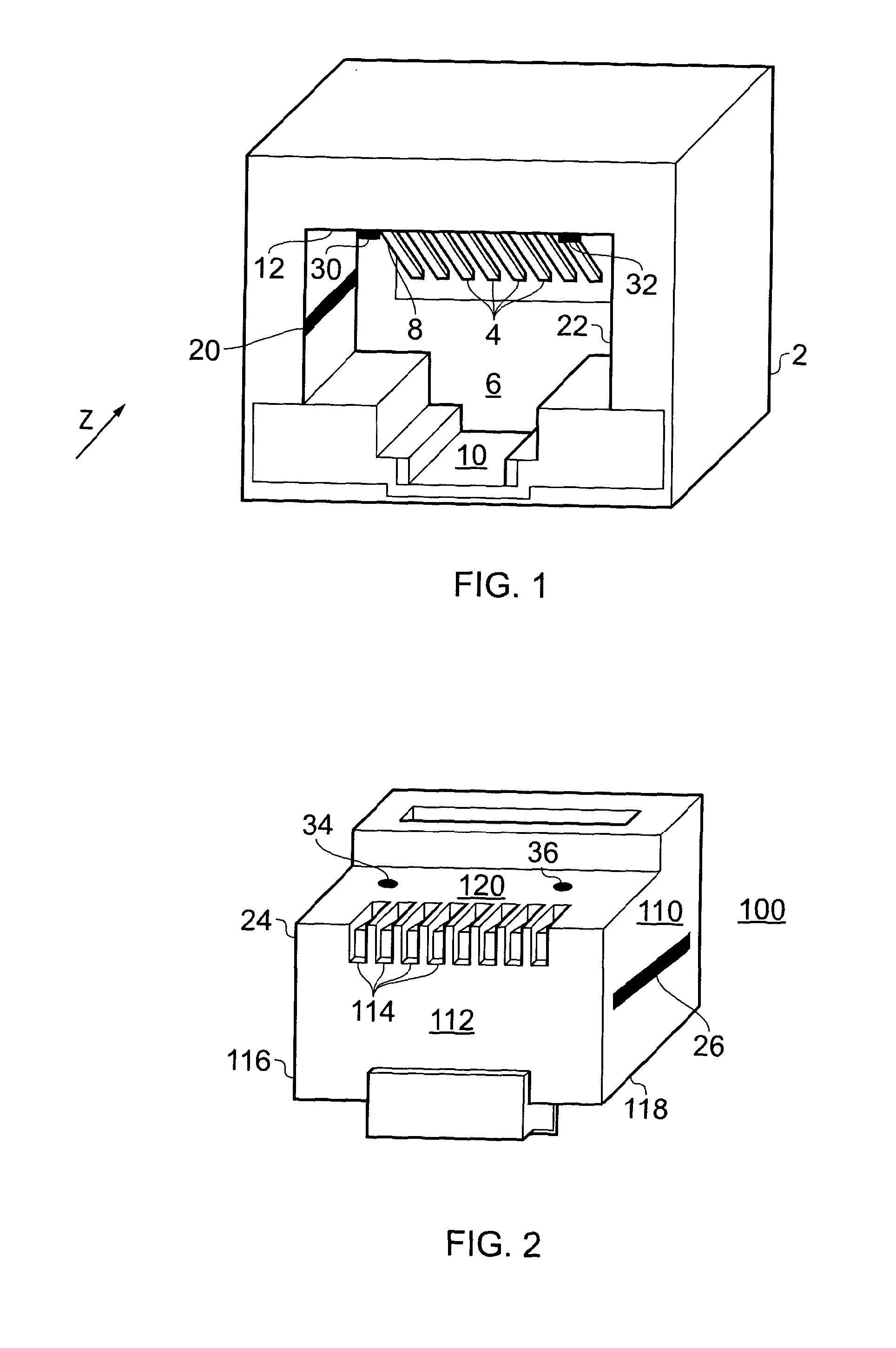
[0064]FIG. 1 shows a socket 2 of an example of one type of connector according to one aspect of the invention. A plug-in area or aperture 6 of the socket is provided which opens against a plug-in direction (Z). A plurality of contact springs 4 disposed in a row next to each other are provided within the aperture 6; the contact springs 4 form an inclined surface 8 projecting into the aperture 6. A second pair of contacts 20, 22 is provided within the aperture 6 of the socket 2. In this example, the second pair of contacts 20, 22 are disposed one on each of two opposite walls of the aperture 6 and consist of a metal strip to provide a power connection from the socket. An additional pair of contacts 30, 32 comprising optical fibre connectors is provided within the aperture 6 on the upper surface 12 of the aperture 6.

[0065]The second pair of contacts 20, 22 for providing power can be located on any internal surface of the aperture 6 providing that the function of any existing features (...


PUM


Abstract

The invention provides a plug (100) which is adapted to be connected to a cable, such as an Ethernet cable, the plug (100) having a generally rectangular cross section and being dimensioned and arranged to be received by an aperture in a socket. On opposite lateral faces of the plug a region, or layer, of conductive material (24, 26) is provided for the transmission of electrical current to/from the cable. Use of the invention therefore permits cabling that has conventionally been used to supply data to also supply power, typically in excess of 200 Watts or so. Such amounts of power are sufficient for operating most equipment that also requires a data connection.

Description

BACKGROUND[0001]This invention relates to a plug for data transmission and / or power supply, and to a socket for insertion of a plug therein.[0002]There are a number of different plug-in connectors that the invention is applicable to, including, but not limited to Ethernet type connectors and USB connectors. Note that the Ethernet connection method as described above commonly uses a standard 8P8C connector which is loosely but erroneously called by the data communications industry an ‘RJ45’. RJ45 in fact describes a rarely used keyed variant of 8P2C with a special wiring arrangement for a telephone application.PRIOR ART[0003]It is known from DE-A-10053843 (Siemens AG) to provide an Ethernet plug-in connector with independent contact elements for providing a voltage supply. In this invention, the voltage supply is provided by contacts located on an outside surface of the socket. Thus, the corresponding plug requires an additional connector to connect with the voltage supply. A problem...

Claims


Application Information

Patent Timeline
Patent Type & Authority Applications(United States)
IPC IPC(8): G02B6/36H01R24/58
CPCH01R24/60H01R2107/00
Inventor PETO, RAYMOND JOHN
Owner POWDAC
Why Eureka
Try Eureka