Temperature abnormality detecting apparatus and method for secondary battery

a secondary battery and temperature abnormality detection technology, which is applied in the field of secondary batteries, can solve the problems of difficult detection of temperature abnormality in the battery from the detected battery pack temperature, abnormal temperature of parts of the battery, and difficulty in accurately detecting a temperature abnormality in the battery pack. , to achieve the effect of simple structure and accurate detection of temperature abnormality

Inactive Publication Date: 2009-02-17
TOYOTA JIDOSHA KK
View PDF7 Cites 22 Cited by
  • Summary
  • Abstract
  • Description
  • Claims
  • Application Information

AI Technical Summary

Benefits of technology

[0016]In view of the foregoing problems, this invention thus provides an abnormality detecting apparatus and method for a secondary bat...

Problems solved by technology

No matter what the cause, because the battery pack that is made up from multiple battery cells can not be cooled evenly, it is difficult to detect a temperature abnormality in the battery from the detected battery pack temperature (i.e., the temperatures of the plurality of battery cells).
Also, when some of the battery temperature sensors have high temperature resistance values that correspond to temperatures that are higher, by a predetermined temperature or more, than the temperatures to which the high temperature resistance values of the majority of the battery temperature sensors correspond, the temperature control device determines that the battery temperature is abnormal, and therefore prohibits the battery from charging or discharging.
Ultimately, in a case when the temperature of each portion of the battery within the battery case is monitored using separate sensors, the temperature of part of the battery is actually abnormally high when the temperatures indicated by some of the sensors are higher than the temperatures indicated by the m...

Method used


Image

  • Temperature abnormality detecting apparatus and method for secondary battery
  • Temperature abnormality detecting apparatus and method for secondary battery
  • Temperature abnormality detecting apparatus and method for secondary battery

Examples


Embodiment Construction

[0037]In the following description and the accompanying drawings, the present invention will be described in more detail in terms of exemplary embodiments. In the description, like parts will be denoted by like reference numerals and referred to by the same nomenclature throughout. Redundant descriptions thereof will be omitted.

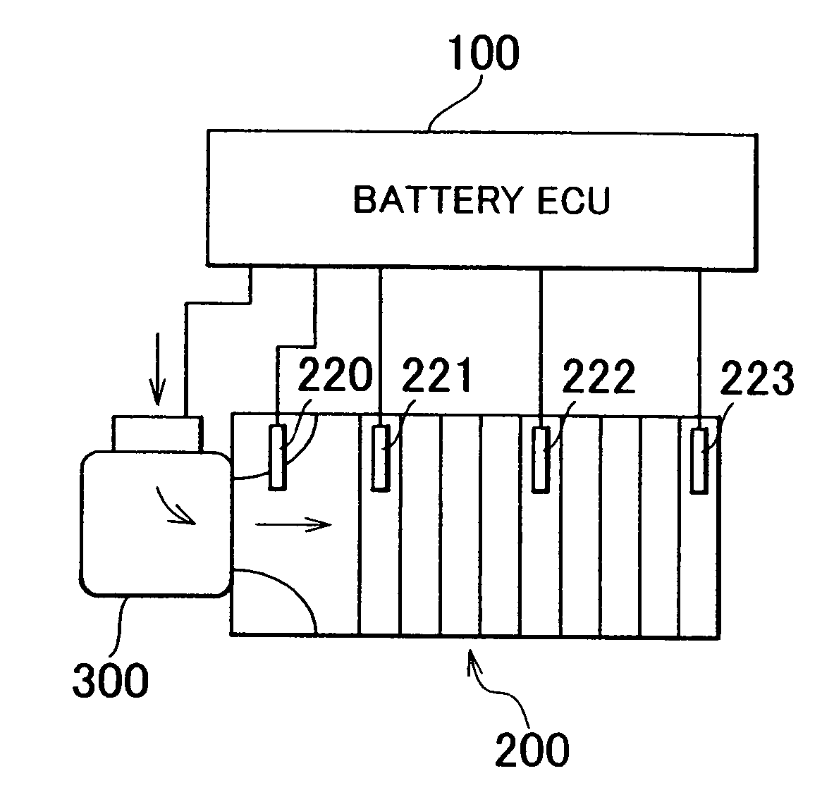
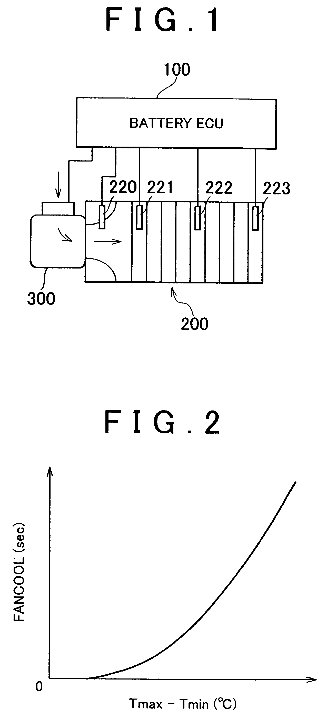
[0038]FIG. 1 is a block diagram of a battery cooling system according to one exemplary embodiment of the invention. As shown in the drawing, this cooling system includes a battery ECU (Electronic Control Unit) 100, a battery 200, and a cooling fan 300 which blows cooling air toward the battery 200. This cooling fan 300 may also draw the cooling air away from the battery 200.

[0039]The battery ECU 100 includes i) a CPU (Central Processing Unit) which executes a program and the like, to be described later, ii) memory for storing the program to be executed by the CPU as well as various threshold values and a map, to be described later, used in the program, iii) a...


PUM


Abstract

A battery ECU includes i) a circuit connected to a plurality of battery temperature sensors provided on a plurality of battery cells which make up a battery, and a cooling fan, the circuit detecting operation of the cooling fan, and ii) a circuit that determines that there is a temperature abnormality in a battery based on the difference between a maximum value and a minimum value of battery temperatures measured by the battery temperature sensors only when the period of time during which temperature increases within a predetermined period of time in the battery temperatures measured by the battery temperature sensors continue to be less than a threshold value is longer than a predetermined period of time, and the cooling fan has been operating for a longer period of time than a suitable cooling fan operating time obtained based on the difference between the maximum value and the minimum value of the measured battery temperatures.

Description

INCORPORATION BY REFERENCE[0001]The disclosure of Japanese Patent Application No. 2003-176757 filed on Jun. 20, 2003, including the specification, drawings and abstract is incorporated herein by reference in its entirety.BACKGROUND OF THE INVENTION[0002]1. Field of the Invention[0003]The invention generally relates to a secondary battery in which a plurality of battery cells are connected together in series. More particularly, the invention relates to a temperature abnormality detecting apparatus and method for a secondary battery mounted in a vehicle.[0004]2. Description of the Related Art[0005]Secondary batteries are typically used in vehicles that are driven either partially or entirely by an electric motor, such as electric vehicles, hybrid vehicles, and fuel cell vehicles. Electric vehicles are driven by an electric motor which runs using power stored in the secondary battery. Hybrid vehicles can be driven either by an electric motor which runs using power stored in the seconda...

Claims


Application Information

Patent Timeline
IPC IPC(8): H02J7/00H02J7/04H01M6/42H01M10/48H01M10/60H01M10/613H01M10/617H01M10/625H01M10/633H01M10/6563H01M10/663H01M50/569
CPCH01M10/486H01M10/5004H01M10/5016H01M10/5022H01M10/5067H01M10/5095H01M6/42H01M10/625H01M10/633H01M10/663H01M10/6563H01M10/613Y02E60/10H01M50/569
Inventor ARIDOME, KOJI
Owner TOYOTA JIDOSHA KK
Why Eureka
Try Eureka