Trailer coupling

a technology of coupling and trailer, applied in the field of trailer coupling, can solve problems such as construction complexity

Active Publication Date: 2005-08-04
ACPS AUTOMOTIVE GMBH
View PDF5 Cites 22 Cited by
  • Summary
  • Abstract
  • Description
  • Claims
  • Application Information

AI Technical Summary

Benefits of technology

[0007] The advantage of the inventive solution is to be seen in the fact that with the provision of a blocking member and a blocking surface a simple possibility is given for blocking the bearing member in the fixing position which offers, in addition, adequate operational safety in the blocking position of the blocking member.
[0051] This may be realized particularly easily in that the receiving member has a surface acting on the at least one blocking member.

Problems solved by technology

In their case, the fixing of the towing element in the fixing position is resolved with considerable ease of operation but in a constructionally complex manner.

Method used


Image

  • Trailer coupling
  • Trailer coupling
  • Trailer coupling

Examples


first embodiment

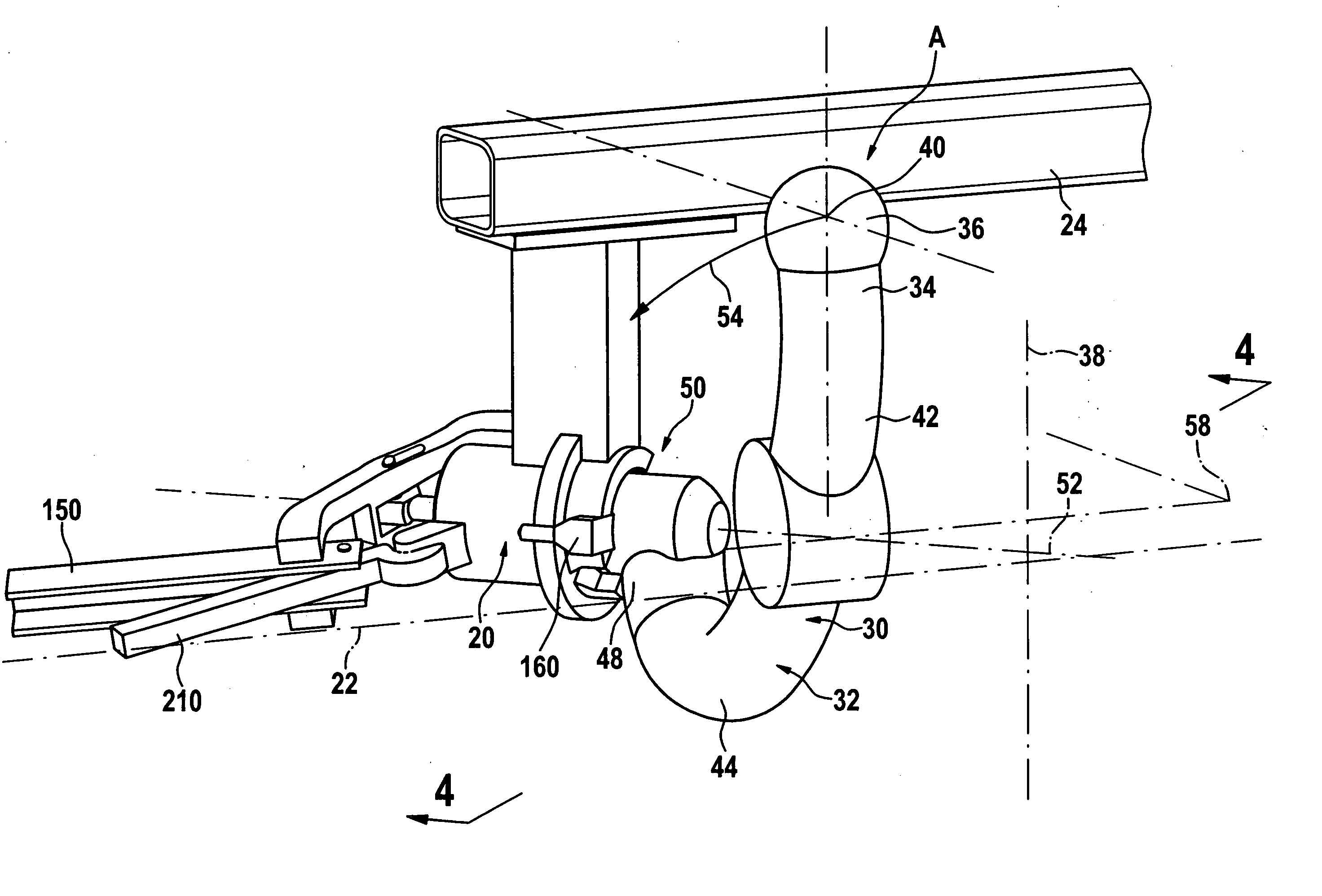
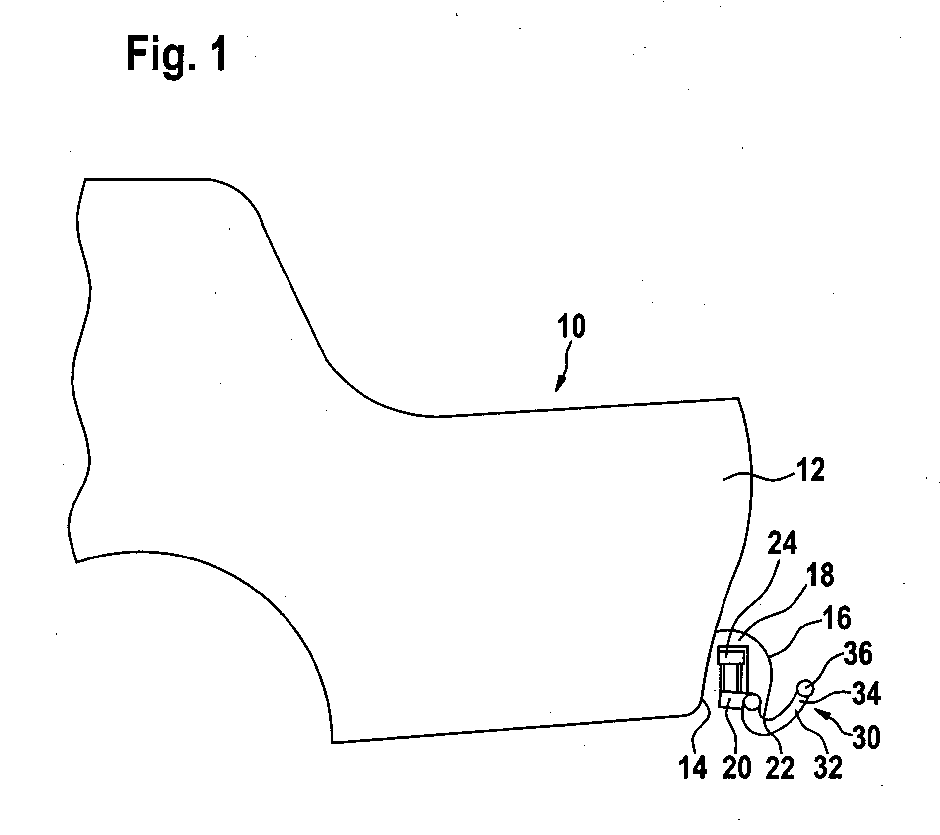
[0089] an inventive trailer coupling is, as illustrated in FIG. 1, mounted on a vehicle body 10, namely between a rear side 14 of the rear end area 12 and a bumper 16. A bearing element 20 of the trailer coupling is arranged in a space 18 formed between the rear side 14 and the bumper 16 and above a lower edge 22 of the bumper 16 and this bearing element is held by a cross bar 24 which is connected to the vehicle body 10 and likewise extends in the space 18.

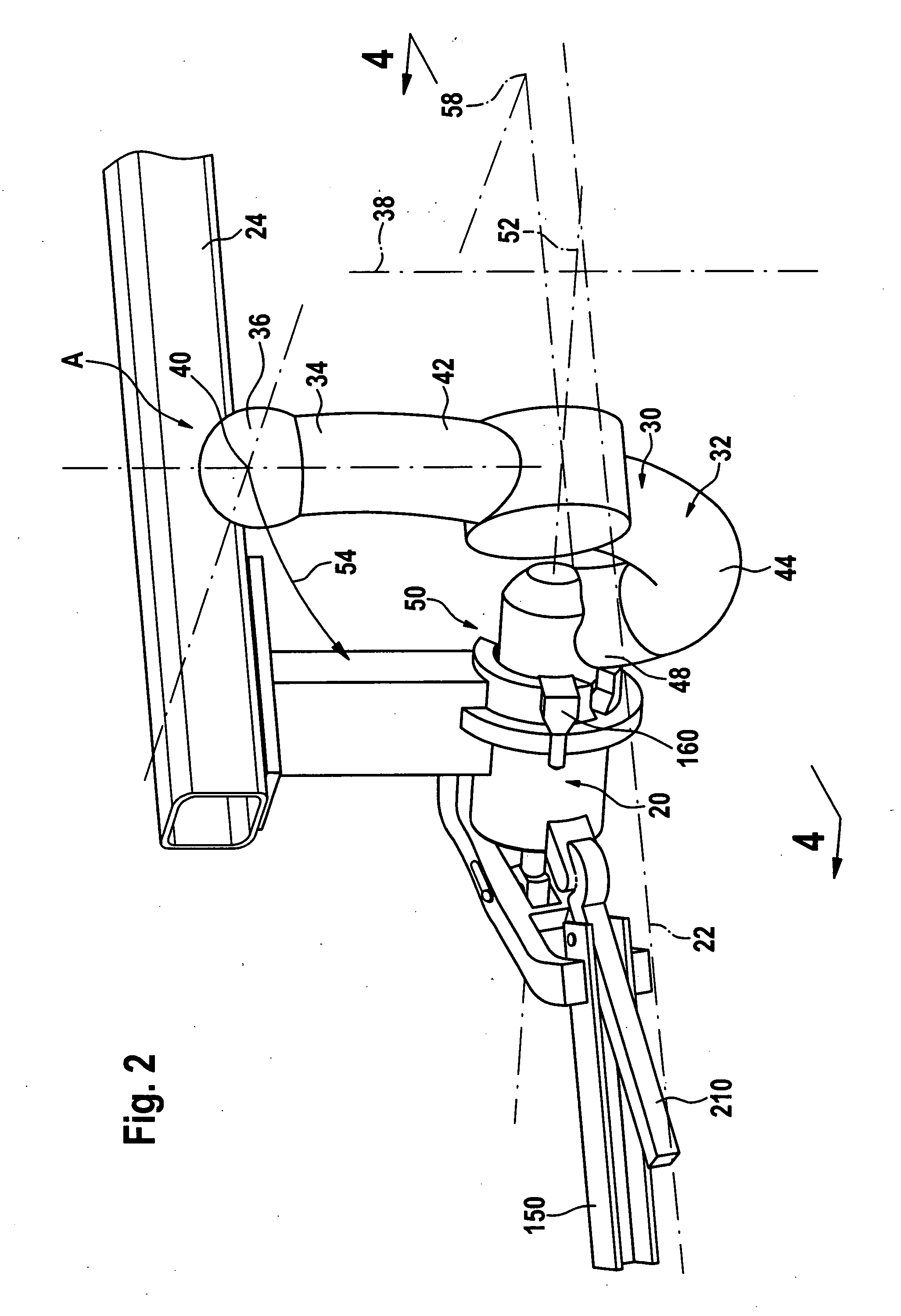
[0090] A towing element designated as a whole as 30 is mounted on the bearing element 20 so as to be movable, wherein the towing element has a ball neck 32 which bears a coupling ball 36 at a first end 34. In an operative position illustrated in FIG. 2, the coupling ball 36 is arranged such that it is intersected symmetrically by a longitudinal central plane 38 of the vehicle body 10 and, therefore, the longitudinal central plane also extends through a central point 40 of the coupling ball 36.

[0091] Furthermore, at least one fir...

third embodiment

[0125] In a third embodiment, illustrated in FIG. 12, the actuating device 140′, in particular, the guide lever 146 cannot be actuated directly by the actuating lever 150 but rather via a cable traction device 230 which creates the possibility of transferring the force to an actuating lever provided at a suitable location via a cable line 232.

[0126] As for the rest, the third embodiment is designed in the same way as the first embodiment and so with respect to the remaining elements reference is made in full to the explanations concerning the first embodiment and the same parts are also given the same reference numerals.

[0127] In a fourth embodiment, illustrated in FIGS. 13 to 16, those elements which are identical to those of the first embodiment are likewise given the same reference numerals and so with respect to the description thereof reference can be made in full to the explanations concerning the first embodiment.

fourth embodiment

[0128] In contrast to the preceding embodiments, the actuating device 140″ in the fourth embodiment is designed as a rotary drive and comprises as actuating element 142′ a toothed rack 242 which is in engagement with a pinion 244 of a drive shaft 246, wherein the drive shaft 246 can be driven by a rotary drive 248 with a free-wheeling means 250 as well as a locking device 252.

[0129] The free-wheeling means 250 is formed by a free-wheeling disk 254 which, as illustrated in FIG. 14, bears an entraining means 256 which engages in an entraining groove 258 of an entraining disk 260 which is mounted so as to be rotatable in relation to the free-wheeling disk 254 and rotatable on the drive shaft 246.

[0130] The entraining groove 258 has, as illustrated in FIG. 15, a first end 262 and a second end 264, between which the entraining means 256 can move freely in the entraining groove 258.

[0131] Furthermore, the entraining disk 260 is provided at its outer circumferential side with a connectin...


PUM


Abstract

In order to provide a trailer coupling for motor vehicles comprising a bearing element, a towing element which can be pivoted in relation to the bearing element between an operative position and a rest position and displaced in the direction of the pivot axis between a pivoting position and a fixing position and a fixing device, with which the towing element can be fixed in position on the bearing element, with a simplified fixing of the towing element on the bearing element it is suggested that the towing element have a bearing member, that the bearing element have a receiving member, in which the bearing member engages at least in the fixing position and in relation to which the bearing member can be moved between the pivoting position and the fixing position in a direction of displacement and vice versa, and that the fixing device have a blocking device which blocks the bearing member with respect to any movement in the direction of displacement relative to the receiving member and has at least one blocking member arranged in one of the elements and movable from a release position in the direction of a blocking position acted upon by a force and at least one blocking surface which is arranged on the other one of the elements and behind which the blocking member engages in the blocking position.

Description

[0001] The present disclosure relates to the subject matter disclosed in German application No. 10 2004 004 503.8 of Jan. 22, 2004, which is incorporated herein by reference in its entirety and for all purposes. BACKGROUND OF THE INVENTION [0002] Trailer coupling for motor vehicles comprising a bearing element, a towing element which is pivotable in relation to the bearing element about a pivot axis of a pivot bearing between an operative position and a rest position and is displaceable in the direction of the pivot axis between a pivoting position and a fixing position at least in the operative position and a fixing device, with which the towing element can be fixed in position on the bearing element so as to be unmovable at least in the operative position and upon reaching the fixing position. [0003] Trailer couplings of this type are known, for example, from DE 100 17 013. [0004] In their case, the fixing of the towing element in the fixing position is resolved with considerable ...

Claims


Application Information

Patent Timeline
Patent Type & Authority Applications(United States)
IPC IPC(8): B60D1/54
CPCB60D1/54B60D1/26
Inventor RIMMELSPACHER, BERNHARDGENTNER, WOLFGANGRIEHLE, JOERGMAYER, GUENTHER
Owner ACPS AUTOMOTIVE GMBH
Why Eureka
Try Eureka