Maintenance device for liquid-ejecting apparatus and liquid-ejecting apparatus

a maintenance device and liquid-ejecting technology, applied in printing and other directions, can solve the problems of complex structure of the maintenance device, and increasing the size of the maintenance devi

Inactive Publication Date: 2007-04-19
SEIKO EPSON CORP
View PDF5 Cites 24 Cited by
  • Summary
  • Abstract
  • Description
  • Claims
  • Application Information

AI Technical Summary

Benefits of technology

[0010] An advantage of some aspects of the invention is that a maintenance device for a liquid-ejecting apparatus and the liquid-ejecting apparatus can be provided in which maintenance components, such as a lock member and a wiper, can be adequately operated even when, for example, a rotational drive source is used in common for a plurality of devices.

Problems solved by technology

As a result, the structure of the maintenance device becomes complex and the size of the maintenance device is increased.
However, since it is necessary to provide the transmission-delaying unit, the structure of the maintenance device becomes complex.
Therefore, if the carriage moves to the home position after the paper feed motor is rotated in the reverse direction by an amount larger than the amount of rotation delayed by the transmission-delaying unit in order to convey the paper sheet, there is a risk that the recording head comes into contact with the wiper or the cap that is moved upward.
Accordingly, even if there are demands for rotating the paper feed motor in the reverse direction by an amount larger than the amount of rotation delayed by the transmission-delaying unit in order to, for example, convey the recording sheet backward (backfeed) for purposes other than cueing in the paper conveying operation, such a demand cannot be satisfied.
As a result, the size of the maintenance device is not largely increased even though the retaining mechanism is additionally provided.

Method used


Image

  • Maintenance device for liquid-ejecting apparatus and liquid-ejecting apparatus
  • Maintenance device for liquid-ejecting apparatus and liquid-ejecting apparatus
  • Maintenance device for liquid-ejecting apparatus and liquid-ejecting apparatus

Examples


first modification

[0183] In the above-described embodiment, the stopper is formed integrally with the slider and moves in association with the vertical movement of the slider. However, it is not necessary that the stopper be formed integrally with the slider. For example, the stopper may also be operated by a retaining mechanism that does not use the moving unit for the cap and be moved from a retaining position to a released when an engaging portion of the carriage pushes another engaging portion as the carriage moves to the cleaning position. In this case, the moving unit for the cap may be structured such that the cap is moved upward by causing the carriage to push a slider. When this retaining mechanism is applied, the stopper follows or moves in association with the movement of the carriage in a predetermined area before the cleaning position and the vertical movement of the cap.

second modification

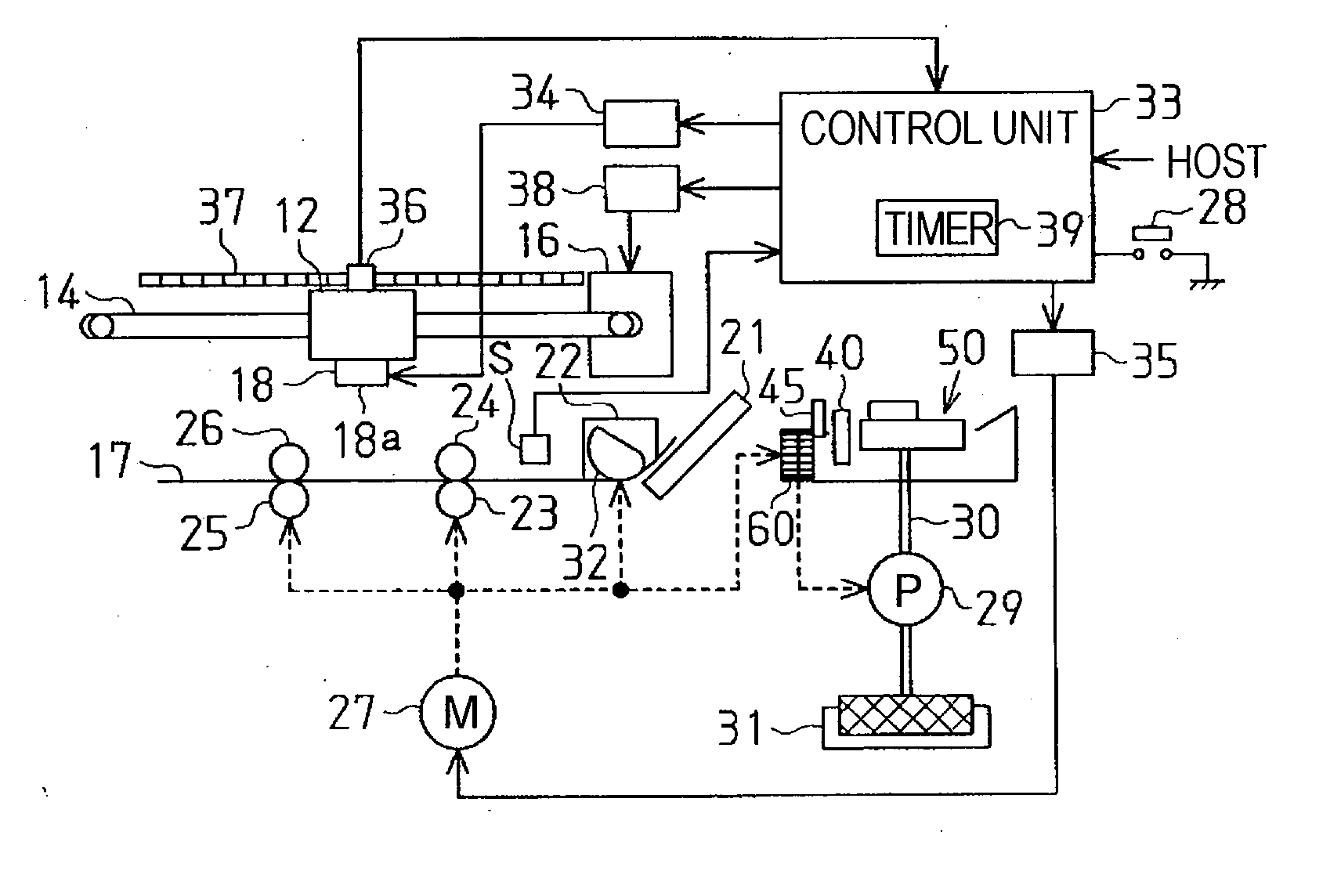
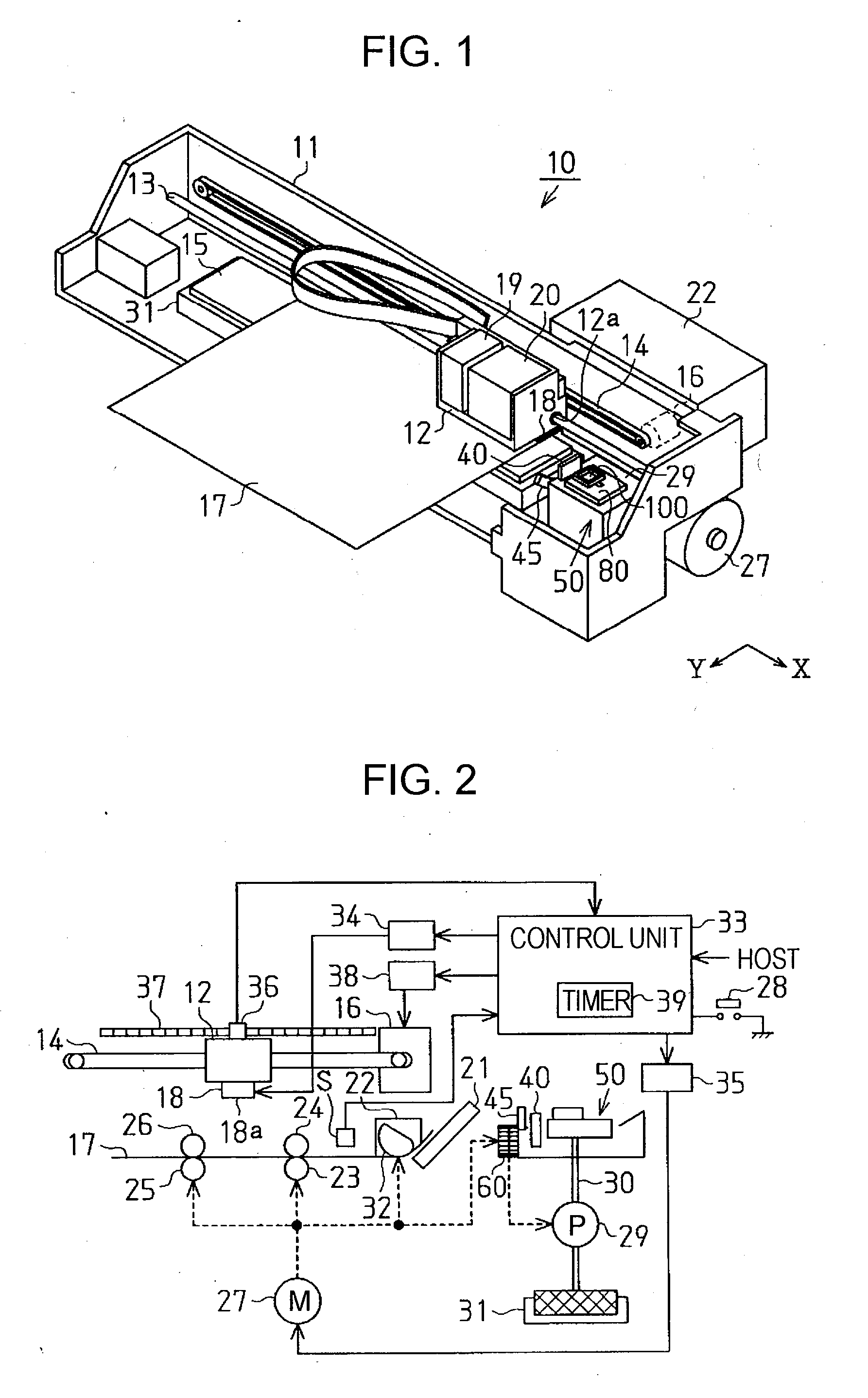
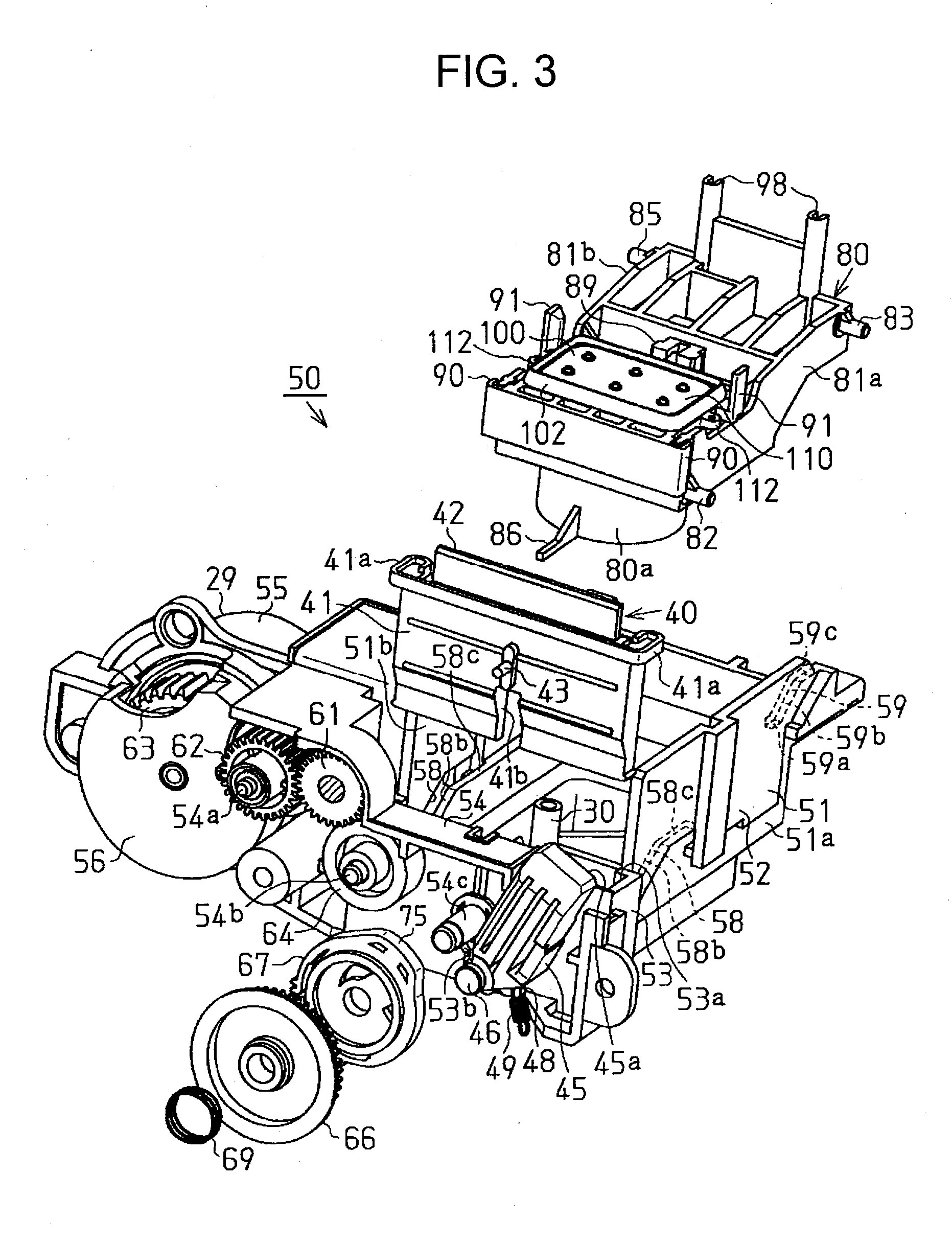
[0184] In the above-described embodiment, the lock lever 45 and the wiper 40 are both locked in an inoperable state by causing the stopper 86 to engage with the movable body (cylindrical cam 67). However, the structure may also be such that only one of the lock lever 45 and the wiper 40 is locked in an inoperable state due to the engagement of the stopper 86. In other words, the maintenance component driven by the power transmitted from the power transmission mechanism 60 may be only one of the lock lever 45 and the wiper 40. Also in this case, one of the lock lever 45 and the wiper 40 is prevented from being operated when the electric motor 27 is driven for operating other devices while cleaning is not performed. For example, the structure may also be such that the lock lever 45 is omitted and only the wiper 40 is operated by the power transmission mechanism 60. Alternatively, the structure may also be such that the wiper is integrated with the cap 100 by providing a wiping member ...

third modification

[0185] The maintenance components operated by the power of the rotational drive source are not limited to the lock lever 45 and the wiper 40. For example, the cap may also be a maintenance component and be operated by the power transmitted by the power transmission mechanism from the electric motor 27 that functions as the rotational drive source. In this case, the lock lever 45 may be omitted and the maintenance components may be the cap and the wiper. Alternatively, the maintenance components may be the lock lever and the cap. In addition, the maintenance components operated by the power transmission mechanism may also be the lock lever, the wiper, and the cap. When the maintenance components are the wiper and the cap, the structure discussed in JP-A-2005-144690 is applied and a stopper is provided on a movable body (a rotating body, a cam body) included in the power transmission mechanism such that the stopper can be retained. In addition, other maintenance components may also be...


PUM


Abstract

A maintenance device installed in a liquid-ejecting apparatus including a movable carriage that has a liquid ejection head performs maintenance of the liquid ejection head and includes at least one maintenance component that reciprocates between an operating position at which the maintenance component engages with the carriage or the liquid ejection head and a standby position at which the maintenance component is disengaged from the carriage and the liquid ejection head; a power transmission mechanism that transmits power input from a rotational drive source to output power for reciprocating the maintenance component between the operating position and the standby position, the power transmission mechanism having a clutch unit on a power transmission path of the power transmission mechanism; and a retaining mechanism including a stopper that moves in association with the movement of the carriage such that the stopper engages with at least one movable body provided on the power transmission path between the maintenance component and clutch surfaces of the clutch unit when the carriage is separated from a cleaning position, and such that the stopper is disengaged from the movable body when the carriage is at the cleaning position.

Description

BACKGROUND [0001] 1. Technical Field [0002] The present invention relates to maintenance devices for liquid-ejecting apparatuses and the liquid-ejecting apparatuses. [0003] 2. Related Art [0004] An inkjet recording apparatus is known as an example of a liquid-ejecting apparatus. The inkjet recording apparatus includes a recording head (liquid ejection head). A printing operation using the recording head is performed by ejecting ink droplets from the recording head while moving the recording head relative to a recording sheet. In order to perform high-quality printing by reliably ejecting the ink droplets from the recording head, it is necessary to perform cleaning of the recording head at a suitable timing during the printing operation or in a period in which the printing operation is not performed so that defects, such as clogging of nozzle holes, can be remedied or prevented. For this purpose, the inkjet recording apparatus generally includes a maintenance device for the recording...

Claims


Application Information

Patent Timeline
Patent Type & Authority Applications(United States)
IPC IPC(8): B41J2/165
CPCB41J2/16511B41J2002/16576
Inventor SHIMAZAKI, JUNHARADA, KOJITOJO, SEIJI
Owner SEIKO EPSON CORP
Why Eureka
Try Eureka