Accordion bottle

a technology of accordion and bottle, which is applied in the direction of transportation and packaging, liquid transferring devices, manufacturing tools, etc., can solve the problems of air or other unwanted fluids entering the container, known devices are not capable of preventing the container from expanding, etc., and achieve the effect of reducing the internal volume of the container and internal volum

Inactive Publication Date: 2012-11-08
SPECIALTY LUBRICANTS CORP
View PDF19 Cites 20 Cited by
  • Summary
  • Abstract
  • Description
  • Claims
  • Application Information

AI Technical Summary

Benefits of technology

[0007]According to another embodiment, the dispensing assembly includes a bellows type container enclosing a fluid containing space, the container having a closed compression end and a dispensing end defining an opening, wherein the compression end is adapted to move toward the dispensing end in response to an applied compressive force; a housing receiving the container in an at least partially enclosing relation, the housing having a dispensing end receiving the dispensing end of the container and providing fluid communication between the fluid containing space of the container and the space external to the container, and the housing having a compression end defining an opening exposing the compression end of the container; a plurality of stop tab receivers defining openings in the housing, the receivers being arranged in one or more rows; and a compression plate received by the compression end of the housing and including a plurality of stop tabs or tab members adapted to mate with corresponding stop tab receivers of the housing.
[0008]According to another embodiment, the dispensing assembly includes a generally cylindrical bellows type container enclosing a fluid containing space, the container having a closed compression end and a dispensing end defining an opening, wherein the compression end is adapted to move toward the dispensing end in response to an applied compressive force; a generally cylindrical housing having a dispensing end and a compression end and defining at least one wall radially spaced from a centrally located longitudinal axis, the wall defining a lateral opening that is continuous with a compression end edge of the wall and adapted to receive a portion of a human thumb, the housing receiving the container in a partially enclosing relation, the dispensing end of the housing comprising a flange member adapted to receive one or more human fingers, and the dispensing end of the housing receiving the dispensing end of the container and providing fluid communication between the fluid containing space of the container and the space external to the container, and the compression end of the housing defining an opening exposing the compression end of the container; a plurality of stop tab receivers defining openings in the housing, the receivers being arranged in two opposing longitudinal rows; and a compression plate received by the compression end of the housing and including a pair of opposing stop tabs adapted to mate with corresponding stop tab receivers of the housing, wherein the stop tabs define a shape having an advancing side and a backstop side, wherein the stop tabs are adapted to advance only from the compression end of the housing toward the dispensing end of the housing, wherein the compression plate contacts the
[0009]According to another embodiment, a dispensing device or assembly includes a container including an internal volume defined by a resilient wall connecting a dispensing end to a compression end, wherein the container includes a first tab member near the compression end extending outwardly from the container, wherein the compression end includes an internal projection extending into the internal volume of the container towards the dispensing end of the container; a housing including an interior defined by a wall connecting a dispensing end to a receiving end, wherein the wall includes a plurality of tab receivers arranged substantially in a row extending along the longitudinal length of the housing, wherein the housing at least partially surrounds the container, wherein the first tab member of the container enters a first tab receiver in the wall of the housing to maintain the container within the interior of the housing; wherein the container dispenses material through the open end when the internal volume is at least partially reduced due to a compressive force moving the compression end towards the dispensing end, wherein the first tab member exits the first tab receiver and enters a second tab receiver, which is located closer to the dispensing end of the housing than the first tab receiver; wherein the first tab member remains in the second tab receiver when the compressive force is removed maintaining the partially reduced internal volume of the container.

Problems solved by technology

However, the known devices are not capable of preventing the container from expanding after a compressive force is removed.
Therefore, air or other unwanted fluids may enter the container.

Method used


Image

  • Accordion bottle
  • Accordion bottle
  • Accordion bottle

Examples


Embodiment Construction

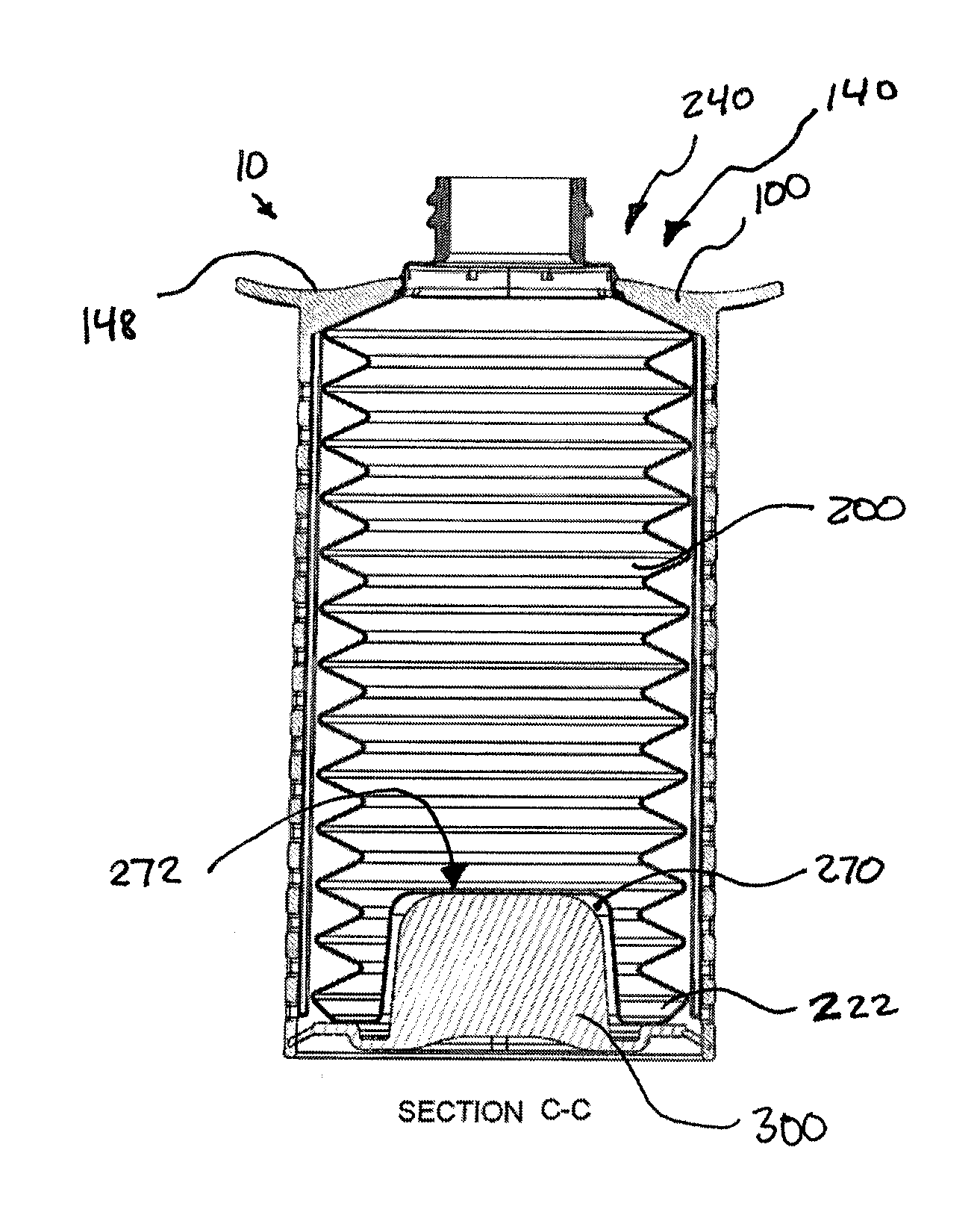
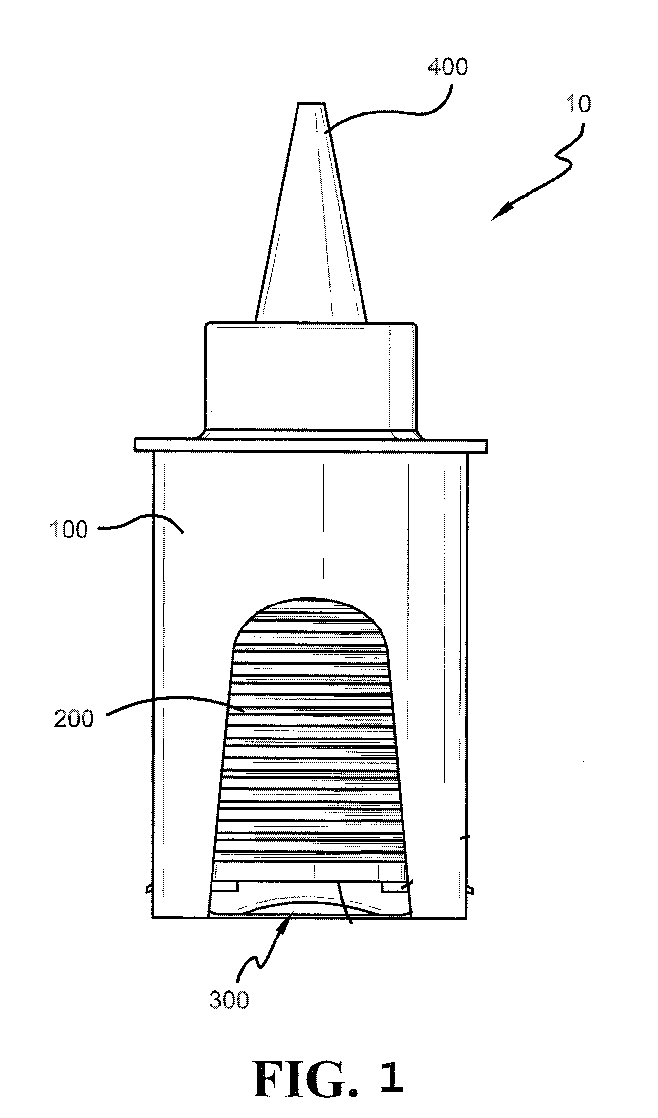
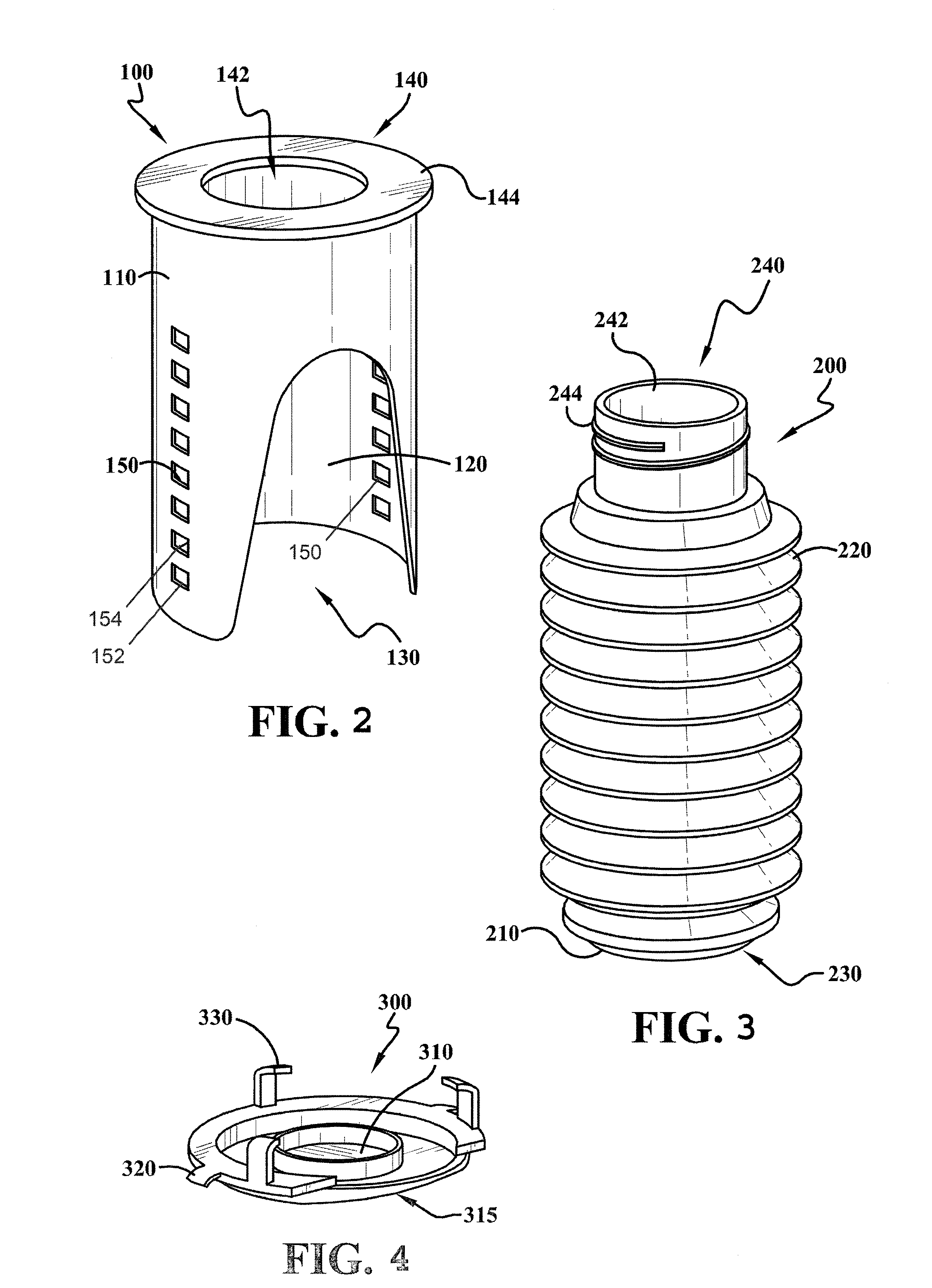
[0035]According to some embodiments, a dispensing device includes a container having a dispensing end and an opposing compression end. The ends are spaced apart and define a longitudinal axis. The container is at least partially enclosed within a housing member. A compression plate is attached to the housing and in contact with the compression end of the container. Applying a compressive force to the compression plate can cause it to move toward the dispensing end, and therefore compress the container and expel fluids contained therein.

[0036]According to some embodiments, a container can include a bottle fabricated from a flexible material, such as an appropriate organic polymer formulation. The dispensing end of the bottle can define an opening for expelling fluids contained therein. In some embodiments, the dispensing end can include an integral nozzle feature, or a means for attaching a nozzle, such as without limitation, threads. The sides of the container define a bellows in a ...


PUM

PropertyMeasurementUnit
compressive forceaaaaaaaaaa
internal volumeaaaaaaaaaa
cylindrical shapeaaaaaaaaaa

Abstract

A dispensing device includes a housing at least partially surrounding a compressible container. The container includes a first tab member received by a first tab receiver in a wall of the housing. The dispensing device dispenses material through an open end of the container in response to a compressive force moving an opposing end of the container towards the open end. As the container is compressed, the first tab member exits the first tab receiver and enters a second tab receiver, which is located closer to the dispensing end of the housing than the first tab receiver. The first tab member remains in the second tab receiver after the compressive force has been removed.

Description

I. BACKGROUND OF THE INVENTION[0001]A. Field of Invention[0002]The present invention relates generally to apparatus and methods for dispensing fluids and more specifically to a device having an adjustable volume for dispensing fluids.[0003]B. Description of the Related Art[0004]Bellows type containers are known in the art for a number of containment and dispensing operations. For instance, it is known to have a generally cylindrical bottle having wall-defining flexible pleats adapted to compress in the manner of a bellows. It is also known to have a dispensing nozzle on such bottles and to fill such bottles with a fluid for dispensing. However, the known devices are not capable of preventing the container from expanding after a compressive force is removed. Therefore, air or other unwanted fluids may enter the container.[0005]Accordingly, there is a need in the art for an apparatus and method to maintain the container in a compressed state after the compressive force has been remove...

Claims


Application Information

Patent Timeline
Patent Type & Authority Applications(United States)
IPC IPC(8): B65D37/00
CPCY10T29/49826B65D83/0055
Inventor BUGENSKE, STEVEN J.BUGENSKE, ROBIN
Owner SPECIALTY LUBRICANTS CORP
Why Eureka
Try Eureka