Method of, and apparatus for, applying flowable material across a surface

a flowable material and surface technology, applied in the direction of additive manufacturing processes, electric/magnetic/electromagnetic heating, manufacturing tools, etc., can solve the problems of low flow rate, low efficiency, and high cost of materials, so as to reduce the quantity of powder which has to be supplied, the quantity of waste is reduced, and the volume of containers is reduced

Active Publication Date: 2010-09-21
EXONE
View PDF12 Cites 159 Cited by
  • Summary
  • Abstract
  • Description
  • Claims
  • Application Information

AI Technical Summary

Benefits of technology

[0009]A further advantage of the invention is that the charging container can be straightforwardly refilled, for example, directly from a conveyor worm because, on account of the charging container being interposed between the stationary supply station and the metering shaft, there is no need for the material to be distributed in the metering shaft already as it is being transferred from the supply station. Rather, according to the invention, the material can be transferred from the supply station into a locally delimited region of the charging container, in which the material can then be distributed on a preliminary basis by means of a suitable distributing arrangement such as a conveyor worm, which is provided in the charging container itself.
[0010]A further advantage is that, on account of the reduced container volumes, the quantities of powder which have to be supplied are reduced. It is thus possible to reduce quantities of waste for, in particular, types of powder of limited service life. When powder types are changed over, the quantities of waste produced are likewise reduced.
[0011]Since uniform distribution of the powder material in the metering shaft means that the levels of compaction do not differ along the metering shaft, it is also no longer the case, on account of the invention, that the metering shaft has to be completely emptied prior to powder being refilled, as a result of which additional quantities of waste can be avoided.

Problems solved by technology

This is the case, in particular, when use is made of powder with poor flow properties, in which case the pile is very steep.
This results in locally different metering quantities in the displaceable supply container of the coating device, metering taking place in the end position of the same, and this may ultimately result in locally different levels of compaction in the building zone and thus in quality fluctuations in respect of strength, finish and component compaction.
However, this produces further quantities of waste.

Method used


Image

  • Method of, and apparatus for, applying flowable material across a surface
  • Method of, and apparatus for, applying flowable material across a surface
  • Method of, and apparatus for, applying flowable material across a surface

Examples


Embodiment Construction

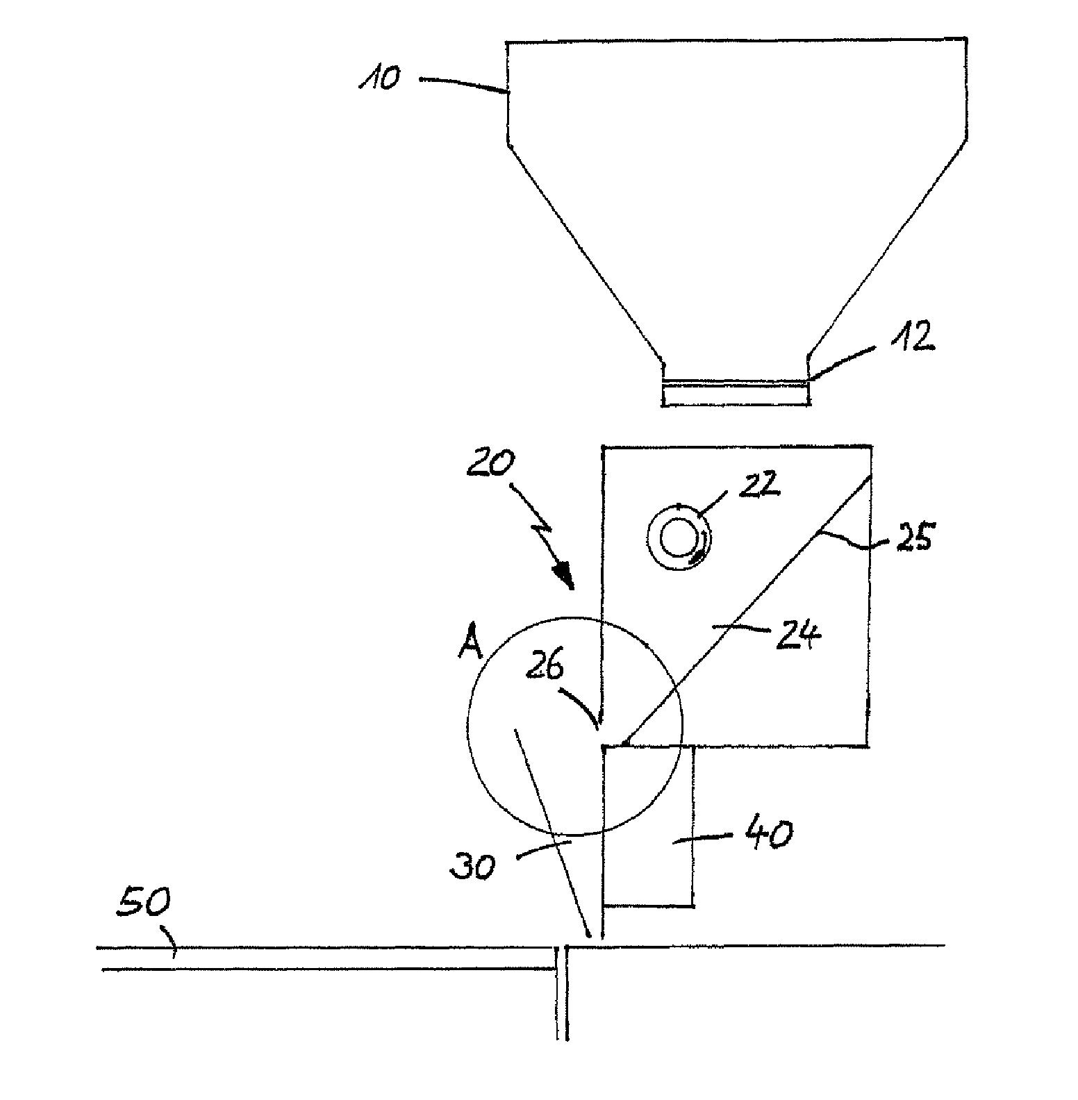
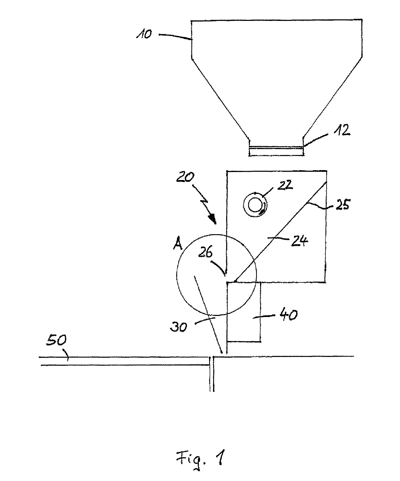
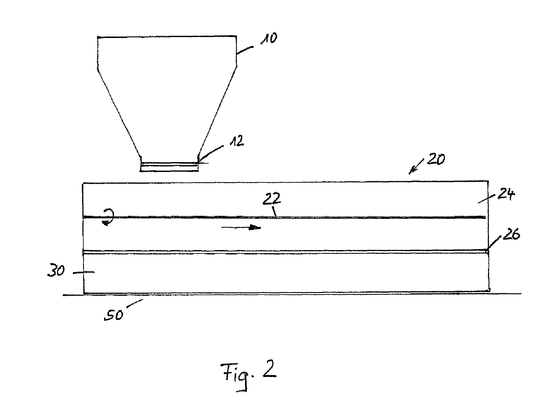
[0020]According to the invention, for the purpose of applying flowable material, in particular particulate or powdery material, across the surface of a substrate 50 in individual layers located one above the other, the flowable material is introduced, from a stationary material supply 10, into a displaceable application apparatus 20 which can be moved back and forth over the substrate 50 and from which the material introduced is discharged downward in continuous layers and distributed uniformly. The application apparatus 20 here has a charging supply, from which a metering shaft is filled such that the filling height of the flowable material in the metering shaft remains constant during the movement of the application apparatus.

[0021]In order, for example in the case of rapid prototyping applications, to apply one above the other uniform layers in which respective cross sections of the three-dimensional object which is to be produced are then selectively bonded or set, the layer-app...


PUM

PropertyMeasurementUnit
lengthaaaaaaaaaa
filling heightaaaaaaaaaa
heightaaaaaaaaaa

Abstract

The invention relates to a method and a device for applying for a flowable material, especially a particulate material, in individual superimposed layers across a support (50), the flowable material being first filled from a stationary feed station (10) into a storage container (24) of an application device. In the application device (30), which travels back and forth across the support, the flowable material is distributed inside the storage container across the entire length of the device and is then metered through a slot into a metering shaft in such a manner that the filling level in the metering shaft remains constant during application of the flowable material from the metering shaft onto the support.

Description

[0001]This application is the National Stage of International Application No. PCT / DE2006 / 002047, filed on Nov. 21, 2006, which claimed the benefit of Application No. 10 2005 056 260.4 filed in Germany on Nov. 25, 2005, which are hereby both incorporated by reference. The International Application No. PCT / DE2006 / 002047 was published on May 31, 2007.I. FIELD OF INVENTION[0002]The invention relates to a method of, and an apparatus for, applying flowable material, in particular particulate material, across the surface of a substrate in individual layers located one above the other.II. BACKGROUND OF THE INVENTION[0003]Such methods and apparatuses are usually used in order to produce three-dimensional objects in layers. A three-dimensional object is produced here by selectively solidifying successive layers of a powdery material at the appropriate locations of a respective cross-section of the object, for example by selectively applying a binder to the respective layer and setting the bin...

Claims


Application Information

Patent Timeline
Patent Type & Authority Patents(United States)
IPC IPC(8): B22F3/00B05D1/12
CPCB29C67/0066B29C67/0077B29C64/135B29C64/153B33Y30/00B33Y10/00
Inventor HOCHSMANN, RAINERSTACHULLA, MARTINKRABLER, BERNDHUHN, STEFANMULLER, ALEXANDERSONNTAG, FRANK
Owner EXONE
Why Eureka
Try Eureka