Separation system to separate phases of downhole fluids for individual analysis

a technology of fluid analysis and separation system, applied in the field of underground formation investigation, can solve the problems of reducing the accuracy of evaluation of a particular phase, requiring significant amounts of capital,

Inactive Publication Date: 2012-11-15
BAKER HUGHES INC
View PDF2 Cites 7 Cited by
  • Summary
  • Abstract
  • Description
  • Claims
  • Application Information

AI Technical Summary

Problems solved by technology

Commercial development of hydrocarbon fields requires significant amounts of capital.
The multi-phase nature of these fluids may reduce the accuracy of evaluation of a particular phase.

Method used


Image

  • Separation system to separate phases of downhole fluids for individual analysis
  • Separation system to separate phases of downhole fluids for individual analysis
  • Separation system to separate phases of downhole fluids for individual analysis

Examples


Embodiment Construction

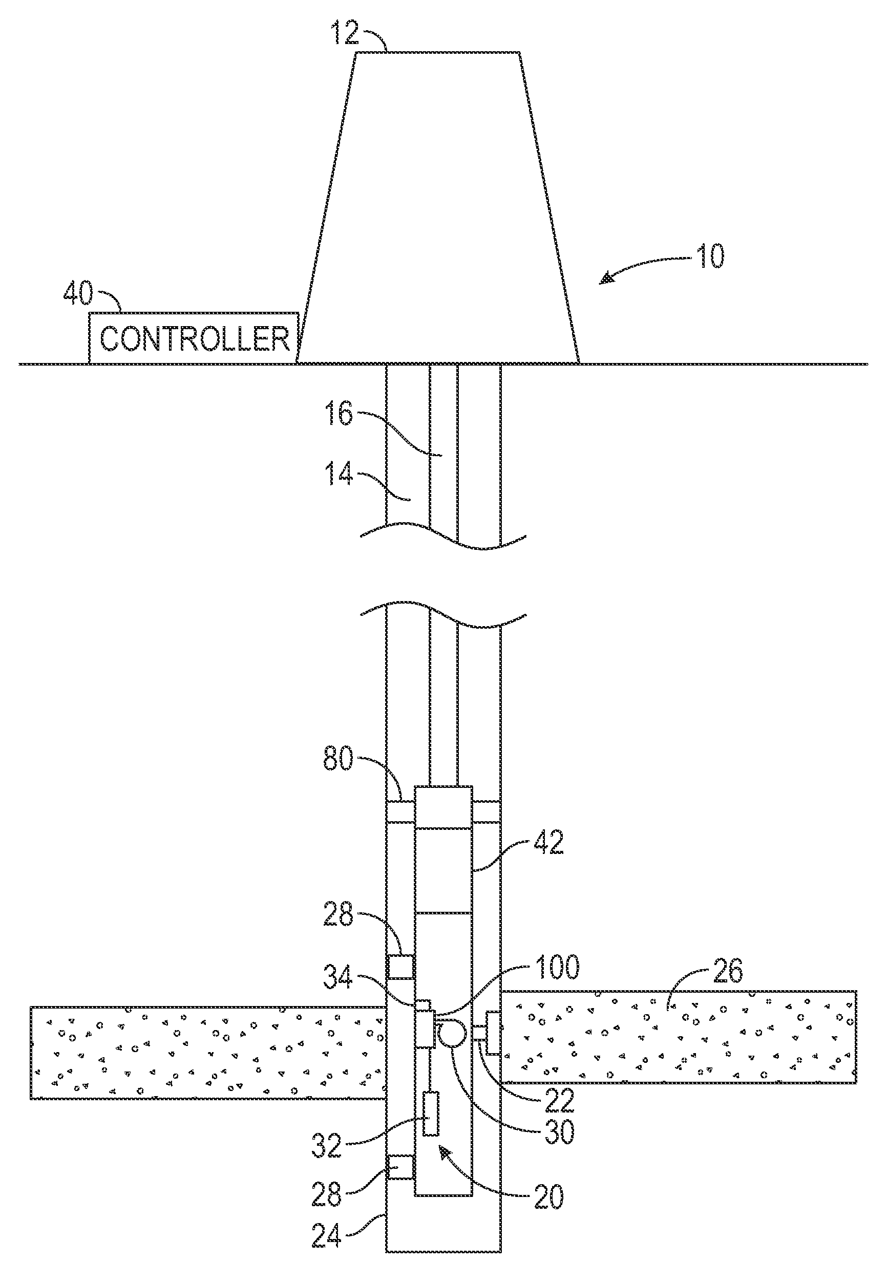
[0014]In aspects, the present disclosure relates to devices and methods to evaluate downhole fluids. As used herein, the term downhole fluid is generally any fluid found in a drilled wellbore and / or any fluid that resides in the formation. Downhole fluids include but are not limited to, naturally occurring fluids such as oil, gas, and water, as well as engineered fluids such as drilling fluids and surface injected fluids. The teachings may be advantageously applied to a variety of systems in the oil and gas industry, water wells, geothermal wells, surface applications and elsewhere. Merely for clarity, certain non-limiting embodiments will be discussed in the context of hydrocarbon producing wells.

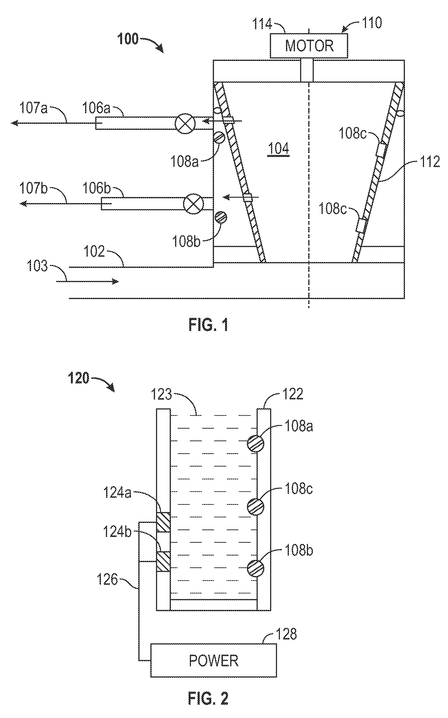
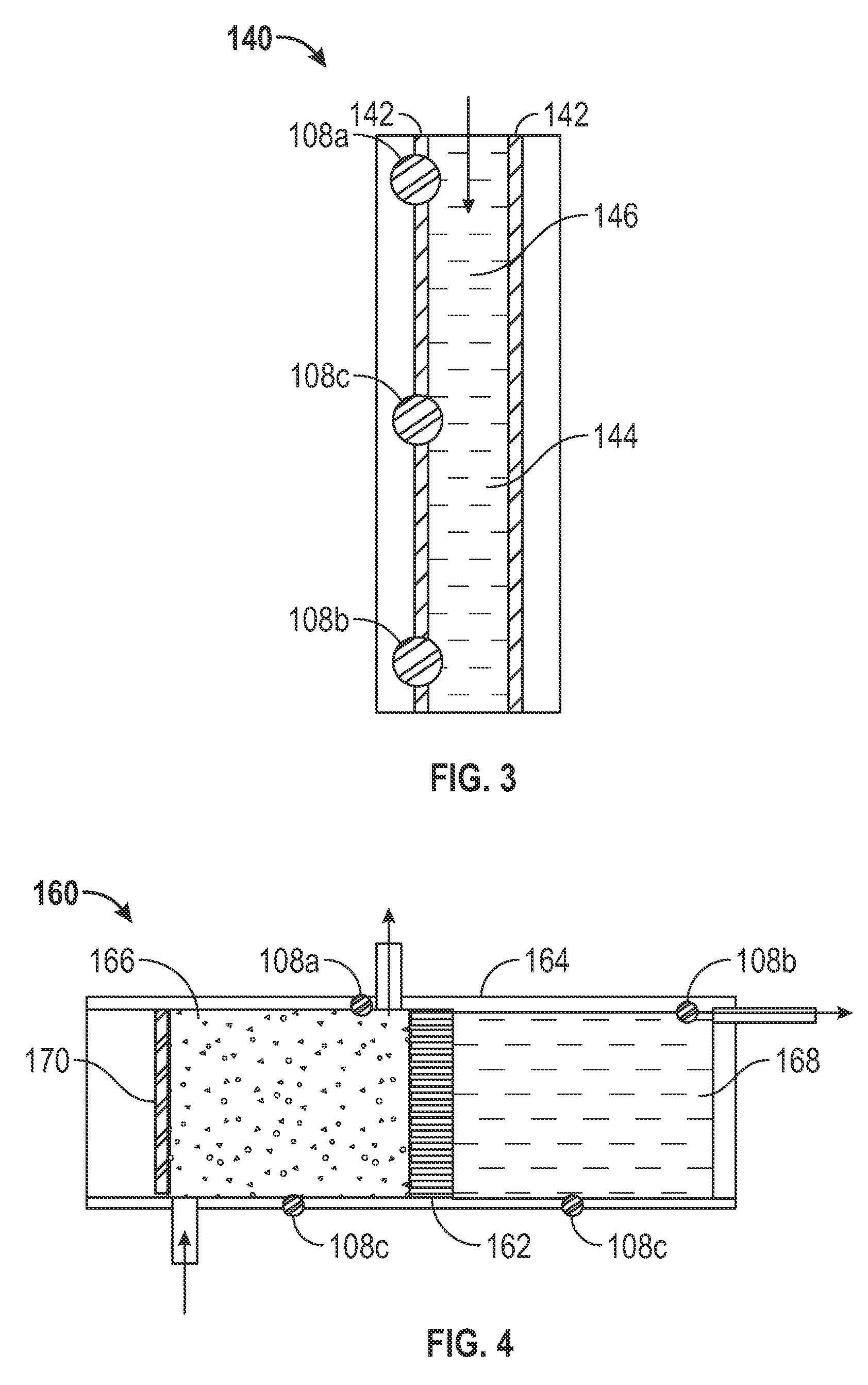
[0015]Referring initially to FIG. 1, there is schematically illustrated one embodiment of a test tool 100 that may be used to actively separate a fluid into two or more homogeneous materials or phases (e.g., a polar phase, a nonpolar phase, an aqueous phase, a liquid hydrocarbon, a gas hyd...


PUM


Abstract

An apparatus for sampling a fluid in a borehole may include a vessel configured to be disposed in a borehole and at least one sensor in communication with one phase of the plurality of phases in the vessel. The vessel separates the fluid into a plurality of phases.

Description

CROSS REFERENCE TO RELATED APPLICATIONS[0001]This application is claims priority from U.S. Provisional Patent Application Ser. No. 61 / 485,961, filed on May 13, 2011, the disclosure of which is incorporated herein by reference in its entirety.FIELD OF THE DISCLOSURE[0002]This disclosure pertains generally to investigations of underground formations and more particularly to systems and methods for evaluating downhole fluids.BACKGROUND OF THE DISCLOSURE[0003]Commercial development of hydrocarbon fields requires significant amounts of capital. Before field development begins, operators desire to have as much data as possible in order to evaluate the reservoir for commercial viability. While data acquisition during drilling provides useful information, it is often also desirable to conduct further testing of the hydrocarbon reservoirs in order to obtain additional data. Therefore, after a borehole for a well has been drilled, the hydrocarbon zones are usually tested with tools that acqui...

Claims


Application Information

Patent Timeline
Patent Type & Authority Applications(United States)
IPC IPC(8): E21B49/08
CPCE21B49/08E21B43/38E21B47/12E21B43/35
Inventor KUMAR, SUNIL
Owner BAKER HUGHES INC
Why Eureka
Try Eureka